MicroLambda MLMY-1071-1 Yig Tuned Oscillator
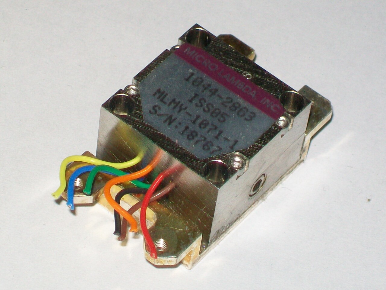
Like many stories this one starts on ebay. Browsing through different offers, I stumbled across a guy selling these miniature YTOs for cheap. Considering I was looking for a reason to play with one for quite a long time, I took the chance and got hold of a bunch of these as the specs are rather impressive: the specified tuning range is 3.75 to 8.23 GHz but the real tuning range is more like 2 GHz to 10.5 GHz.
This model appears to be a bespoke version of the off-the-shelf version with the part number MLMY-0408. Luckily the seller provided a datasheet for the unit:
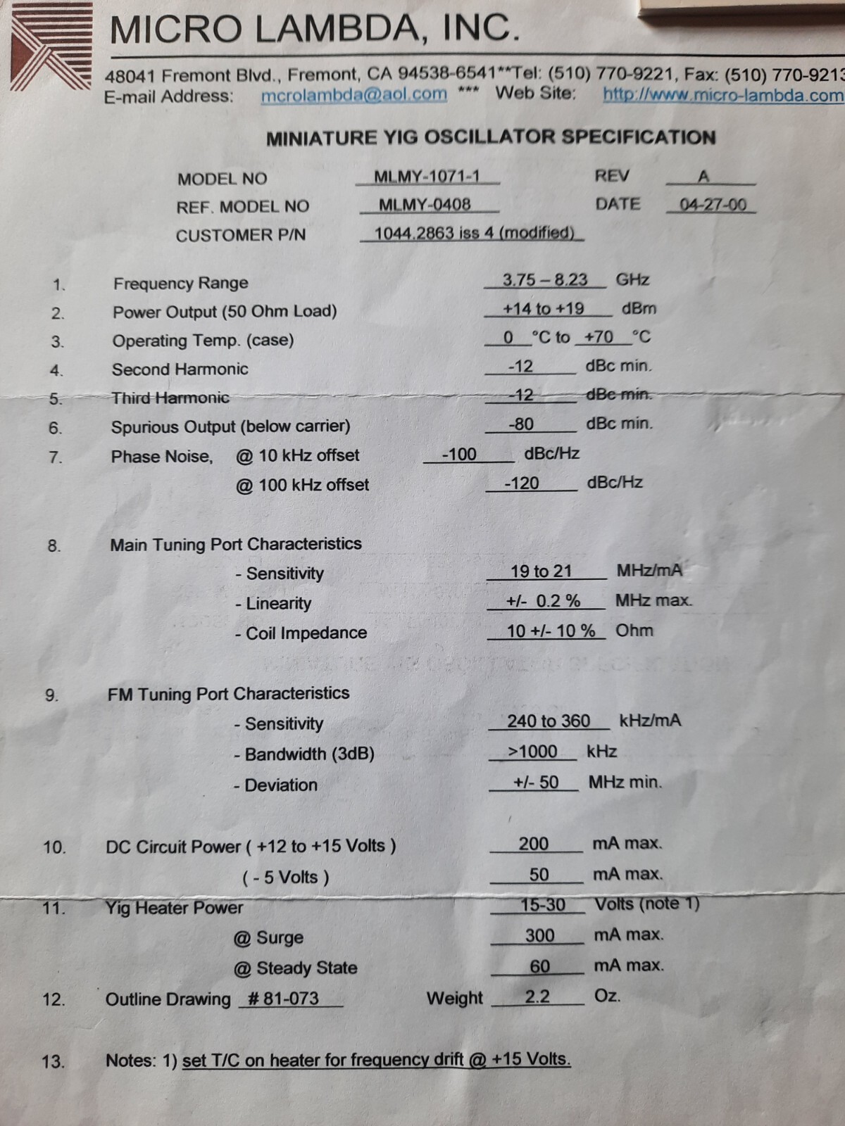
The Pinout is shown in the following table:
| color |
function |
| black |
heater 15 .. 24V relative to GND |
| green |
-5V (internal FET bias) |
| blue |
+15V (NEVER APPLY WITHOUT -5V ON GREEN PIN) |
| orange |
main coil - |
| yellow |
main coil + |
| red |
FM coil - |
| brown |
FM coil + |
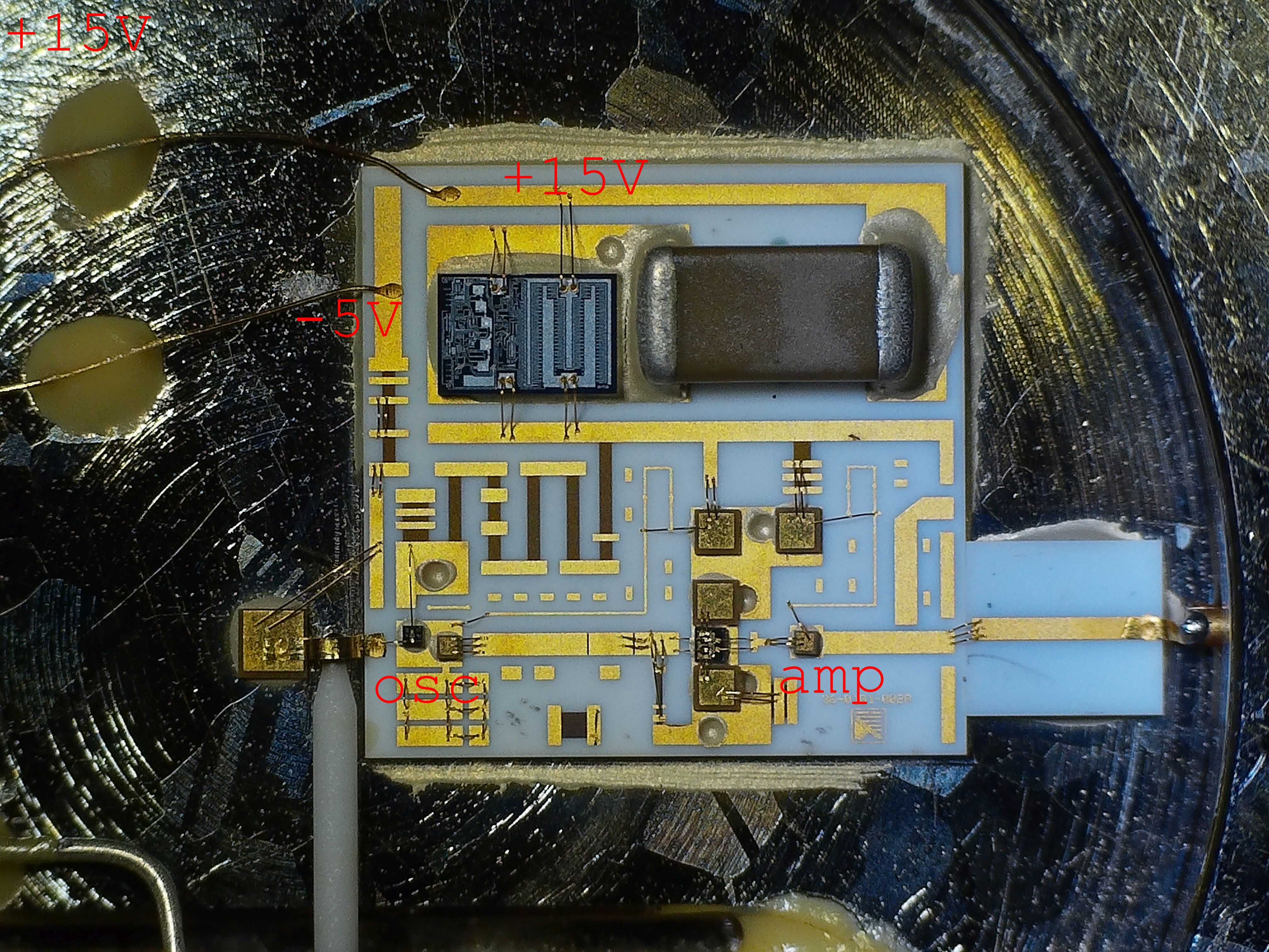
The top part containing the tuning and FM coil is held in place with four screws. Removing them reveals the hybrid circuit on a ceramic substrate.
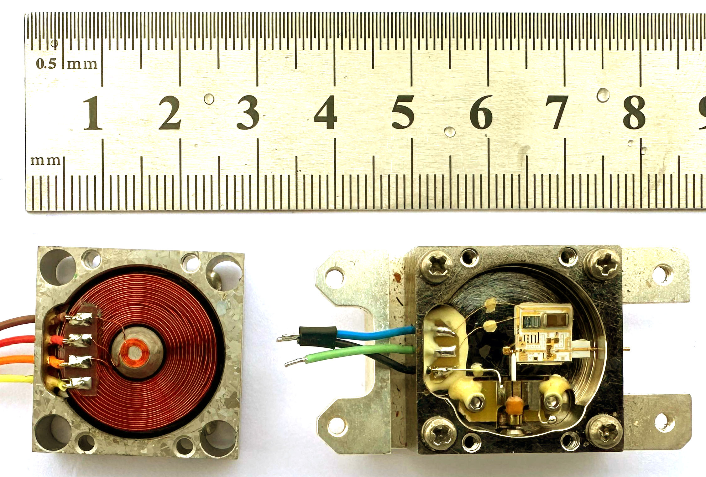
The integrated circuit die on top is most likely a linear voltage regulator regulating the +15V rail down to a more appropriate voltage for the oscillator and amplifier transistor. Right next to it sits a ceramic filter capacitor for the +15V input.
On the left side of the ceramic substrate the connection of the -5V bias for the oscillator transistor is bonded to the substrate. Apparently the bias is only required for the oscillator transistor, not for the amplifier.
On the bottom left you can see the YIG sphere mounted on its holder. Bottom right you can see the microstrip line going to the rf output.
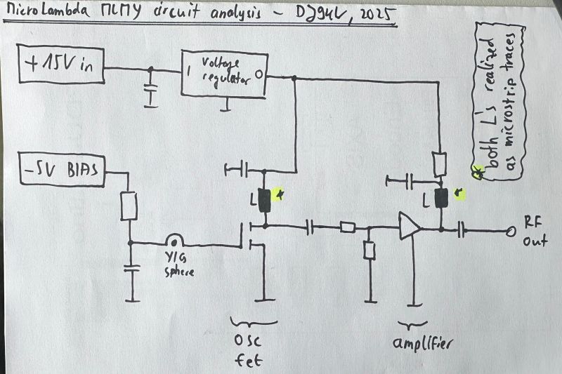
The circuit is easy to analyze and has plenty of matching adjustment options, all done by hand. All in all an amazing design and rather tiny, no wonder these things are that expensive when new!

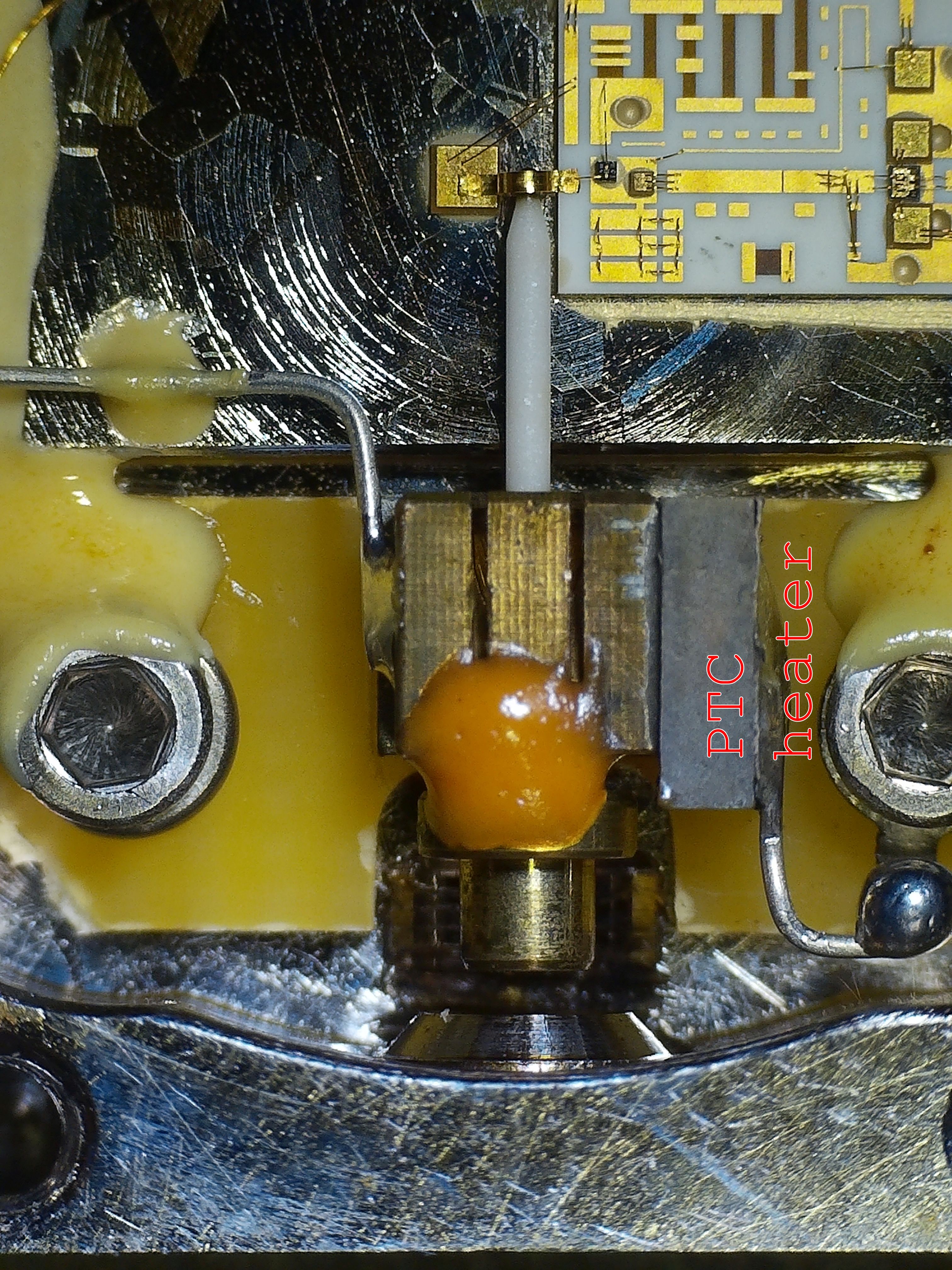
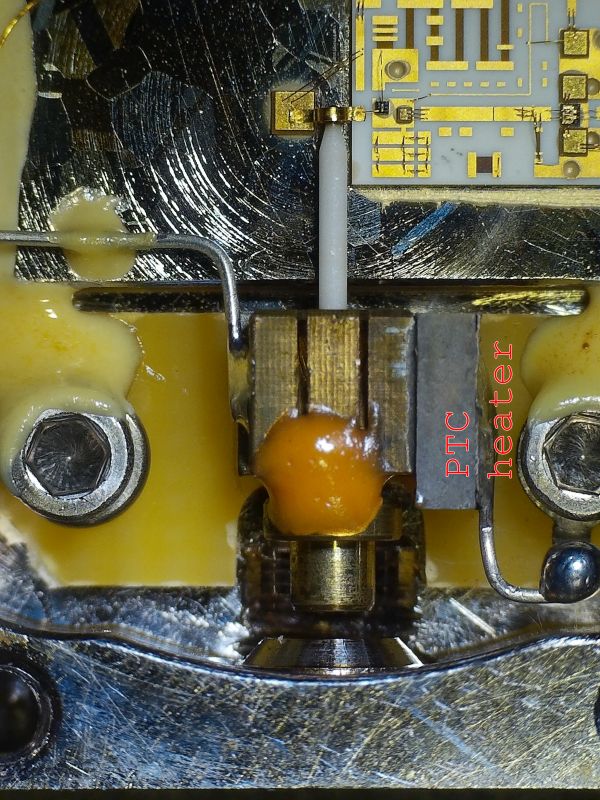
The next picture shows the PTC heating element attached to the YIG holder:
The main tuning coil has a resistance of 10 ohms, this is the current - frequency relation on this oscillator:
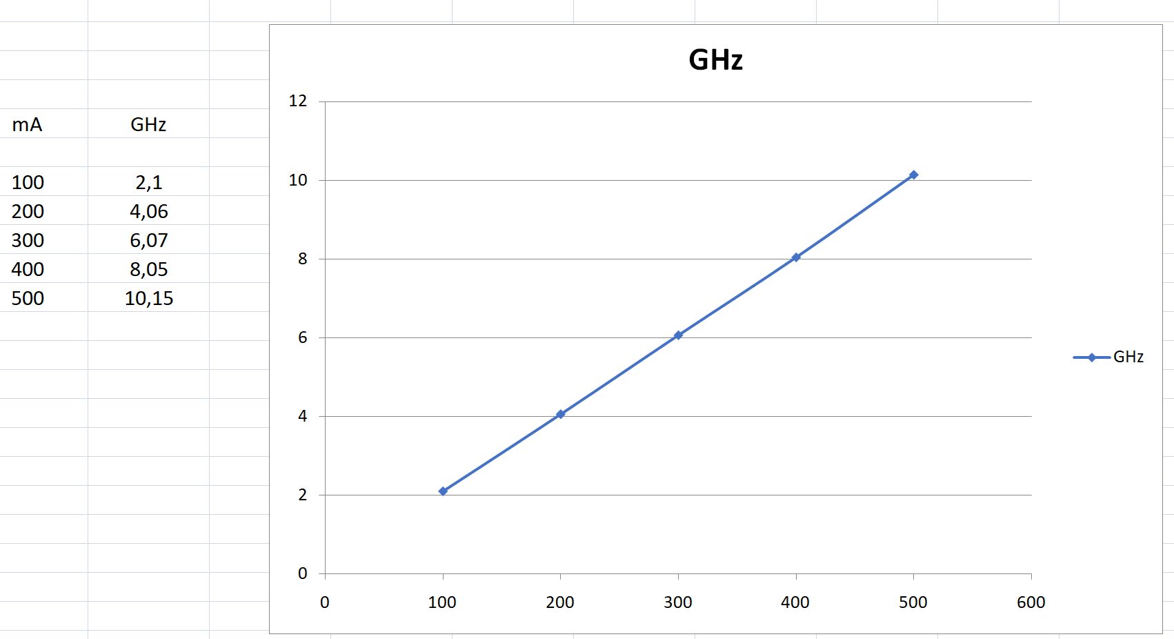
What a pity, the tuning curve is rather different from the
HP 5986-7906 YTOs
, at least I can't substitute them without further modifications... That's the moment where LTspices comes in handy for rescue! A quick simulation later, I've designed (at least in theory) a circuit which translates the 97 to 150 mA HP tuning coil current (red trace in simulation) to 150 .. 400 mA MLMY tuning coil current (green trace in simulation):
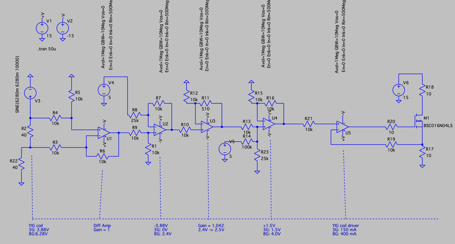
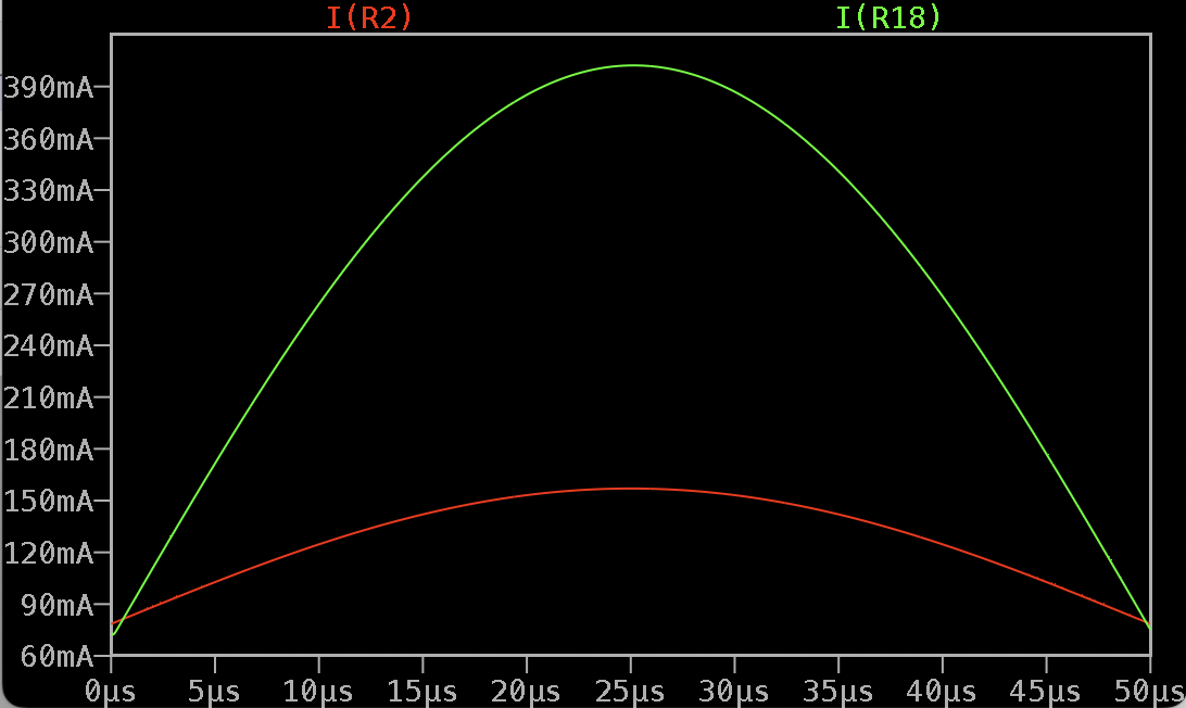
Might require some compensation and might interfere badly with the switched filtering across the HP tuning coil but as semiconductors are rather cheap nowadays I'll give it a shot and see how it performs in real life.
(c) DJ9KW, 07/2025