HP 5086-7906 YIG oscillator bonanza
Starting up one of the probably faulty spectrum analyzers on my bench, the unit is greeting me with one of these rather common error messages: 334 LO AMPL and several 35x errors.
Instead of measuring, I do a quick google search which reveals that all of those errors are quite common with these units and usually related to a dead, dying or weak yig tuned oscillator (YIG, YTO). The microcircuits' oscillator transistor seems to lose gain and eventually stop oscillating at all. There are many YTOs from HP which are all compatible and use the same microcircuit inside, only the biasing PCB on top of the oscillator seems to have gone through different revisions. Unfortunately, they all tend to fail in exactly the same way...
The (non-comrehensive) list of (to my experience) compatible YTOs:
5086-7906
5086-7903
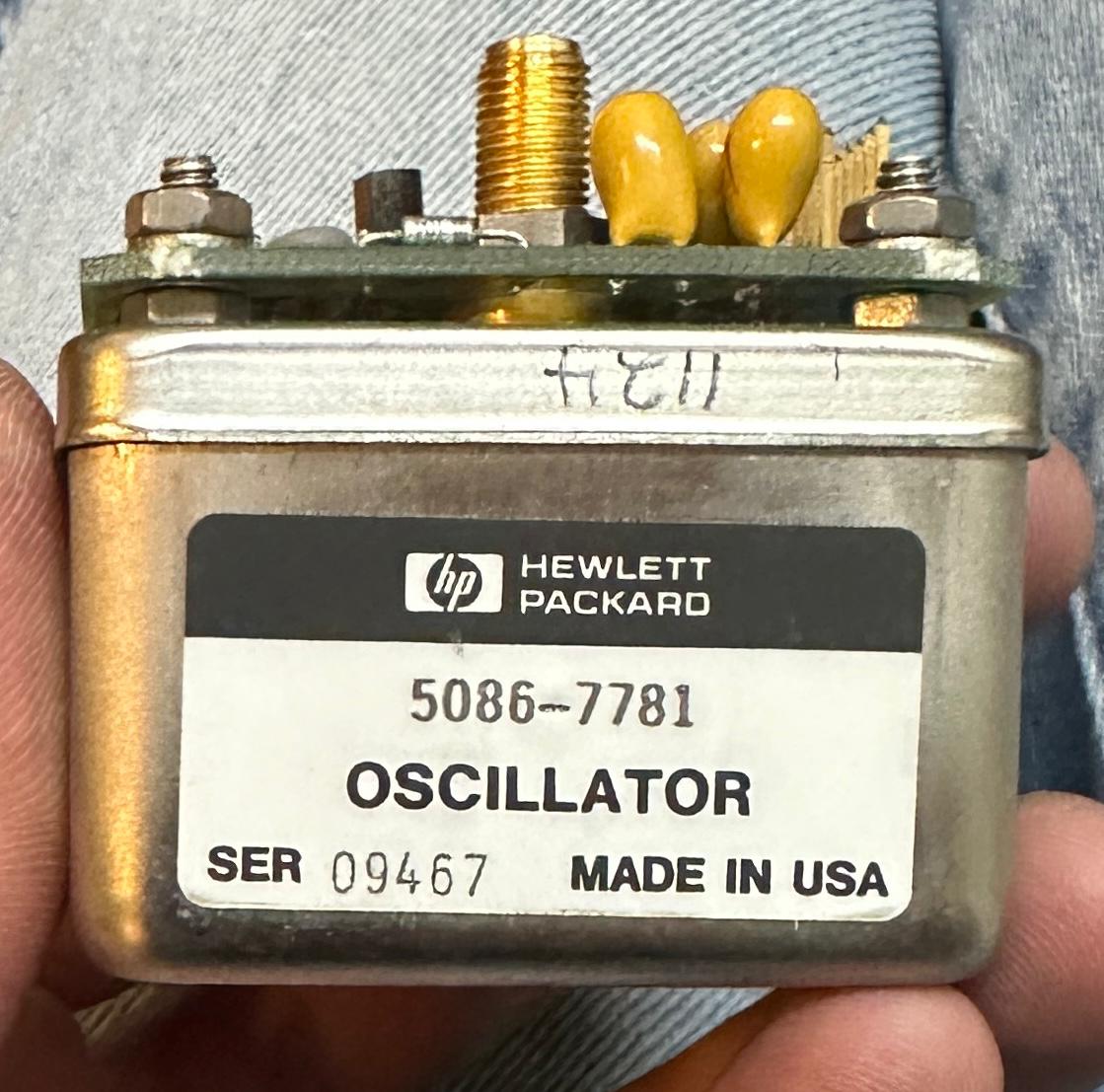
5086-7781
I should know better, but of course I do a quick search for replacement parts but a working YTO is more than I spent for the whole analyzer and you never know when it starts to die.
As far as I know these YTOs were used in the HP 856x and 859x series of spectrum analyzers and in the 8753x series of network analyzers.
Some technical info on the YTO:
Specified frequency range: 3.0 .. 6.8 GHz but as with most YTOs the actual range is quite bigger
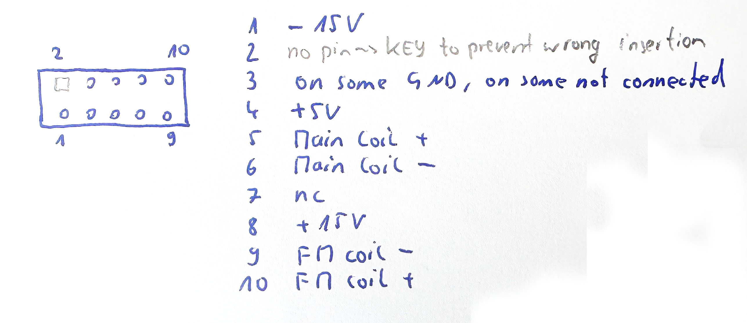
Supply voltage: +5V, -15V and +15V. Be aware that the HP engineers prepared a trap for young players and omitted the ground connection on some units on the 10pin idc socket, the YTO relies on the case for connecting ground!!!! NEVER APPLY +5V WITHOUT APPLYING THE OTHER VOLTAGES AS RUNNING THE YTO WITHOUT THE BIAS VOLTAGES MIGHT DESTROY IT
Output level: approx. +15 dBm with a well behaving one, a somewhat tired one I have is at +10dBm on its output.
Main coil resistance: 40 ohms
Main coil current: 97 mA for 3 GHz and 157 mA for 8 GHz
FM coil resistance: 2 ohms
The pinout of the HP IDC connector on the bias board on top of the oscillator is as follows:
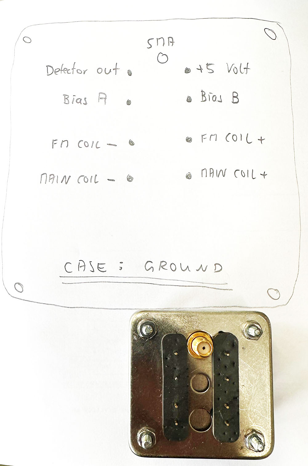
The job of the bias board is to measure the output level of the YTO (a diode rectifies a coupled portion of the rf generated) and adjust the bias of the oscillator transistor accordingly to achieve a flat frequency response over the full frequency range. This is achieved by comparing the voltage from the rf detector to a set value (pots on pcb) and adjusting the voltage to the osc transistor. Removing the bias pcb reveals eight pins connecting to the inner parts of the YTO.
ATTENTION: THERE IS A WEBSITE WHICH SHOWS THE PINOUT OF BOTH THE IDC CONNECTOR ON THE BIAS BOARD AND THE PINOUT OF THE YTO MODULE ITSELF, THE PINOUT FOR THESE 8 PINS IS WRONG ON THIS WEBSITE! THEY SWAPPED THE PINS FOR THE MAIN AND FM COIL, THE VOLTAGE READINGS FOR THE BIAS PINS ARE SUSPECT, TOO!!!!
The (verified and tested) pinout between the biasing pcb and the YTO itself:
The voltages on the pins "Bias A" and "Bias B" depend on the condition of the YIG oscillator and the selected optput frequency, as the bias is used to ensure a stable and flat output amplitude over frequency...
| Pin |
weak YTO (+11 dBm) |
| Bias A |
796 mV |
| Bias B |
1800 .. 2050 mV |
| Detector |
-172 mV |
(c) DJ9KW, 07/2025