A reverse engineering deep dive into a Trixell Pixium 3543ez x-ray detector panel
Let's start with the legal stuff, just to be on the safe side:
Disclaimer
Purpose and Intent
This website documents the reverse engineering efforts on the Trixell/Thales Pixium 3543 EZ digital X-ray flat panel detector. The entire content of this website is provided strictly for educational purposes and is driven purely by technical curiosity and the desire to understand how these sophisticated embedded systems work.
This project aims to repurpose decommissioned medical equipment for non-medical applications such as material testing and research. There is no intent whatsoever to:
. Violate any intellectual property rights, patents, trade secrets, or proprietary information held by Trixell, Thales, or any affiliated companies and OEM integrators
. Enable circumvention of safety mechanisms or regulatory controls
. Encourage unauthorized use of medical equipment
. Provide information that could compromise patient safety in clinical environments
Medical Equipment Warning
This documentation is NOT intended for medical applications.
If you are working with a detector panel that is part of a certified medical imaging system:
. Do not apply any modifications, configurations, or techniques described here
. Do not attempt to bypass or alter the proprietary control software
. Medical X-ray equipment must operate under proper certification by responsible authorities (FDA, CE marking, national health agencies, etc.)
. Any modification to certified medical equipment voids its certification and may violate medical device regulations
. Patient safety depends on properly maintained and certified equipment
The information presented here is exclusively for panels that have been permanently removed from medical service and are being repurposed for industrial, educational, or research applications outside the scope of medical device regulations.
Radiation Safety
Working with X-ray equipment involves serious health hazards from ionizing radiation. This website assumes that anyone working with such equipment:
. Is fully trained in radiation safety principles and practices
. Understands the biological effects of ionizing radiation
. Has access to appropriate dosimetry and monitoring equipment
. Operates under applicable radiation protection regulations
. Has implemented proper shielding and safety interlocks
. Takes full responsibility for protecting themselves and all persons in the vicinity
Recommended safe testing approach: For protocol development and software testing, consider using a visible light source (torch/flashlight) with masking film placed on the detector panel. The scintillator layer will respond to visible light, allowing you to verify detector functionality without any radiation exposure. This method is strongly encouraged for all development and debugging work.
During all testing phases described on this website, X-ray sources should remain physically disconnected.
No Warranty
All information, code, configurations, and documentation provided on this website are offered "as is" without any warranty of any kind, express or implied. This includes, but is not limited to, warranties of merchantability, fitness for a particular purpose, accuracy, or non-infringement.
The author(s) make no guarantees that:
. The information is complete, accurate, or current
. Any procedures will work on your specific hardware revision
. Following these procedures will not damage your equipment
. The techniques described are suitable for any particular application
You assume all risks associated with using any information from this website.
Limitation of Liability
Under no circumstances shall the author(s) of this website be liable for any direct, indirect, incidental, special, consequential, or punitive damages arising from:
. Use or inability to use the information provided
. Equipment damage or malfunction
. Personal injury or radiation exposure
. Regulatory violations or legal consequences
. Any other damages whatsoever
Intellectual Property Acknowledgment
Trixell, Thales, Pixium, Pixrad and all related product names, trademarks, and trade dress are the property of their respective owners. This website is an independent documentation effort and is not affiliated with, endorsed by, or sponsored by Trixell, Thales, or any of their partners, subsidiaries, or OEM customers.
All reverse engineering work documented here was performed through clean-room analysis of publicly observable behavior, network protocols, and configuration files-conducted in the spirit of interoperability research and education.
Contact
If any individual or organization believes that content on this website infringes upon their rights or causes harm in any way, please contact me immediately by sending an email to 3543re [AT] dj9kw.de . I am committed to addressing legitimate concerns promptly and will take appropriate measures upon notification.
By accessing and using this website, you acknowledge that you have read, understood, and agree to this disclaimer.
Last updated: November 2025
... and now for the technical side of things:
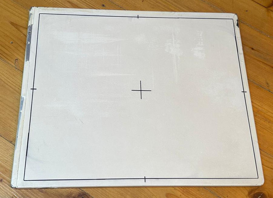
The adventure started when I got my hands on a used, somewhat beat up Trixell 3543EZ detector panel. For a long time I was interested in how these detectors work and I always wanted to tinker around with one. Years ago I watched a teardown video by mikeselectricstuff on youtube, but other than that there aren't many resources available regarding this type of equipment.
What's my goal? It would be nice if I could get the panel to run in autonomous mode, capturing an image upon pointing my flashlight at the detector surface and storing it in its internal memory. Furthermore I'd like to either be able to download the images via ssh or get the thing to send the images to my rudimentary Python based (and fully untested) DICOM server.
When the panel arrived at my door I realized that any kind of operation would be quite difficult as this type of detector heavily relies on the proper setup and acquisition software. The panel should have initially shipped with a copy of the Trixell / Thales tool called "Pixrad", presumably version 6. And - as you already might have guessed - the computer with the proper software was scrapped three days before I got the panel... what a pity! And it seems absolutely impossible to find the software required anywhere on the internet. On 4shared I discovered a few files from different Pixrad installations but the files are incomplete... So if anyone reading this has access to the software and is willing to support my research I would be glad if you could drop me a message :-) Any wireshark pcap captures of the radiology software communicating with the flat panel would be highly appreciated, too!
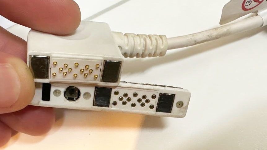
It was already late in the evening but I couldn't resist to have a peek at the detector. I got the original batteries and the ethernet cable which has spring-loaded pogo-pins which are pulled against a mating connector surface on the detector panel by strong magnets, nice attention to detail!
After charging one of the batteries way too short I inserted it into the detector, connected the ethernet cable and hoped for the best. The manuals suggest an IP range within the 192.168.1.x range and an IP scan proved this expectation: the panel was reachable using its default IP, 192.168.1.5.
Scanning the open ports below 1000 revealed only port 22 (ssh). Trying to connect as user root worked but I got stuck at the password prompt. Bummer, it's not that easy :)
So what is the first thing to do? Don't turn it on, take it apaaaaart!
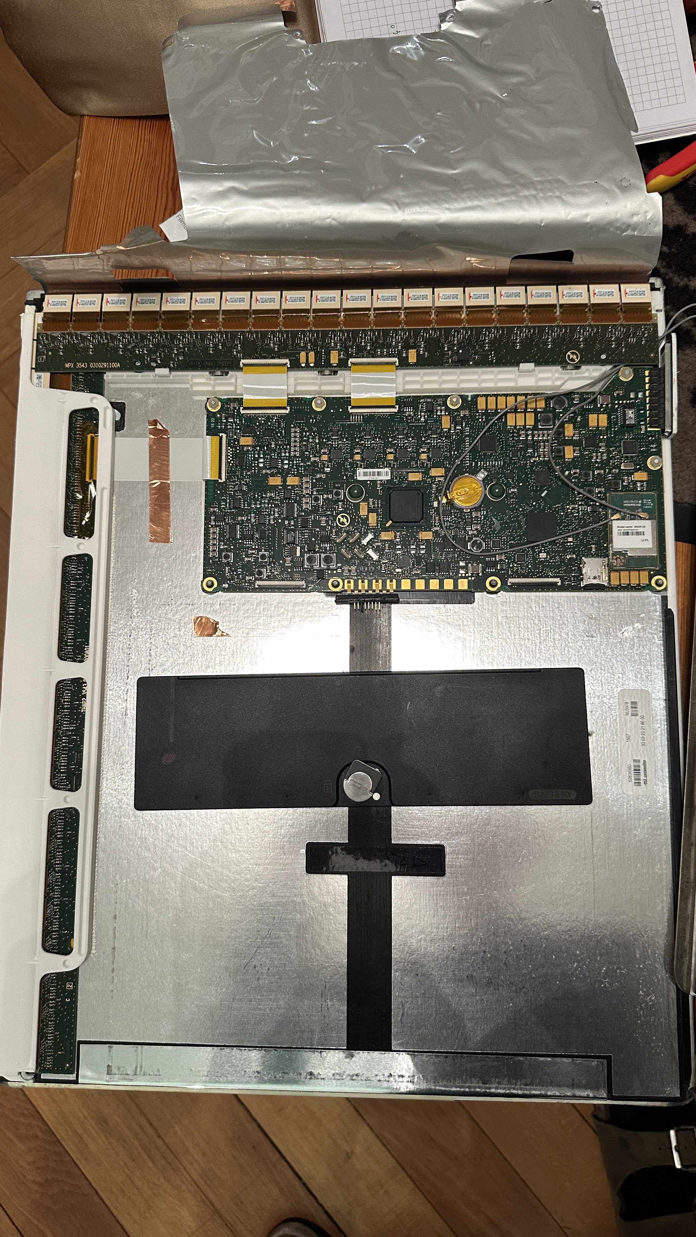
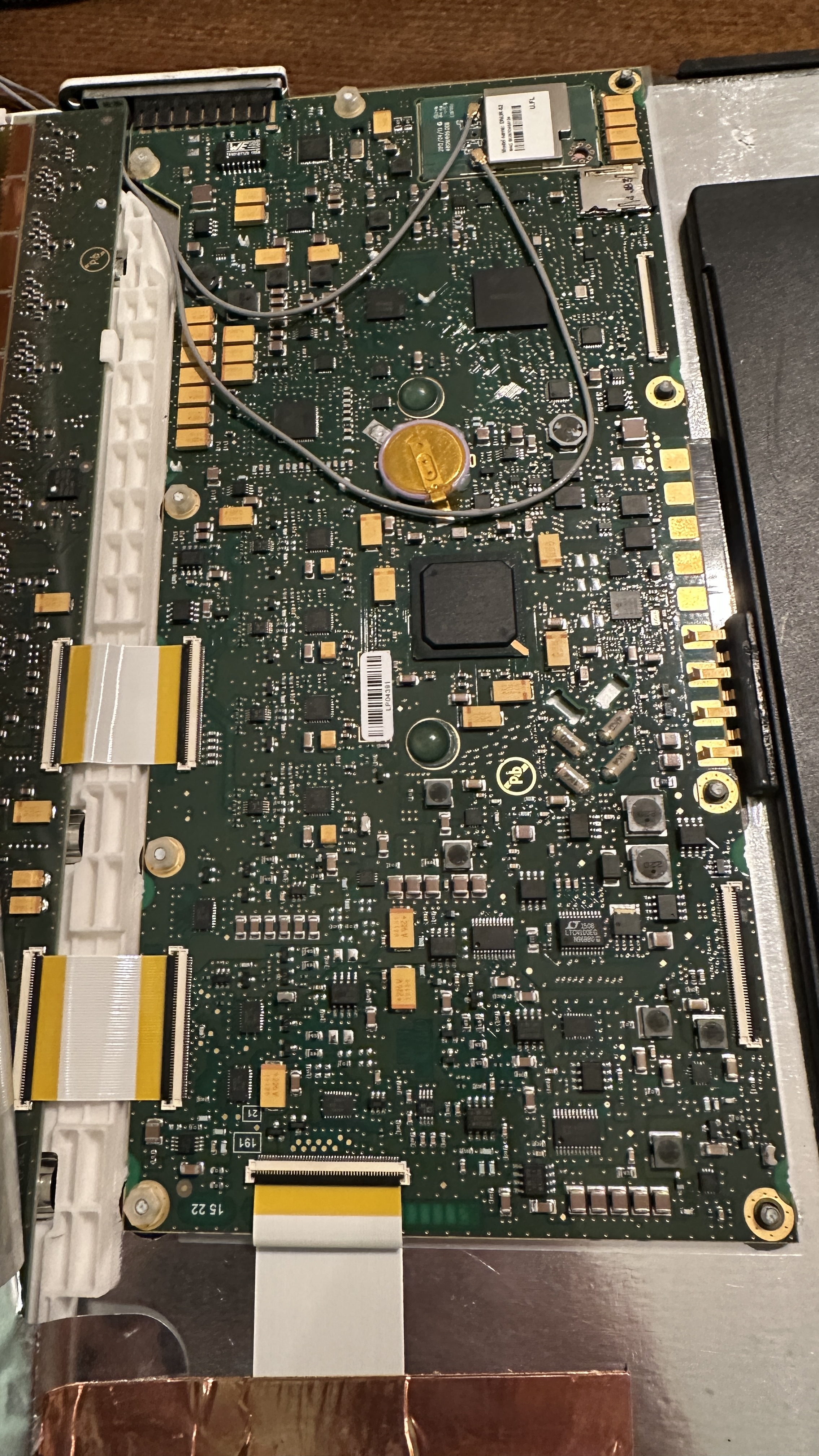
Thanks to the beat up condition the screws on one end of the detector were quite obvious. I removed all of them and was impressed by the build quality: All screws have machined nuts which fit in a milled shape on the detector. After removing the screws and some trial-and-error, I realized that I have to remove the ethernet/LED assembly on the side and afterwards I could slide out the electronics from the tubular metal frame.
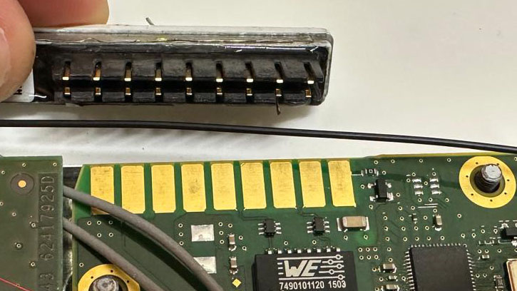
The connector subassembly which slides onto the main pcb with springloaded contacts
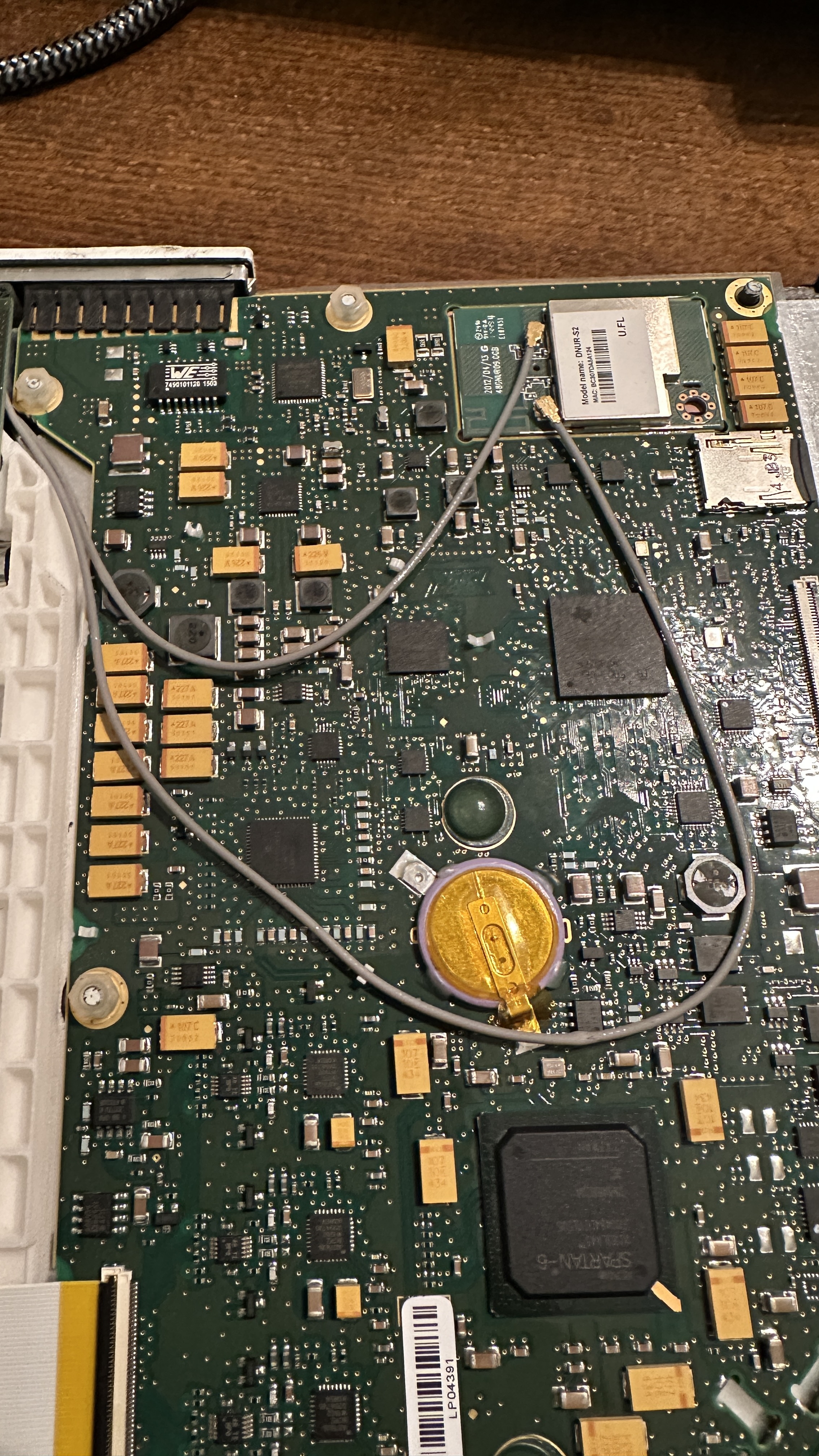
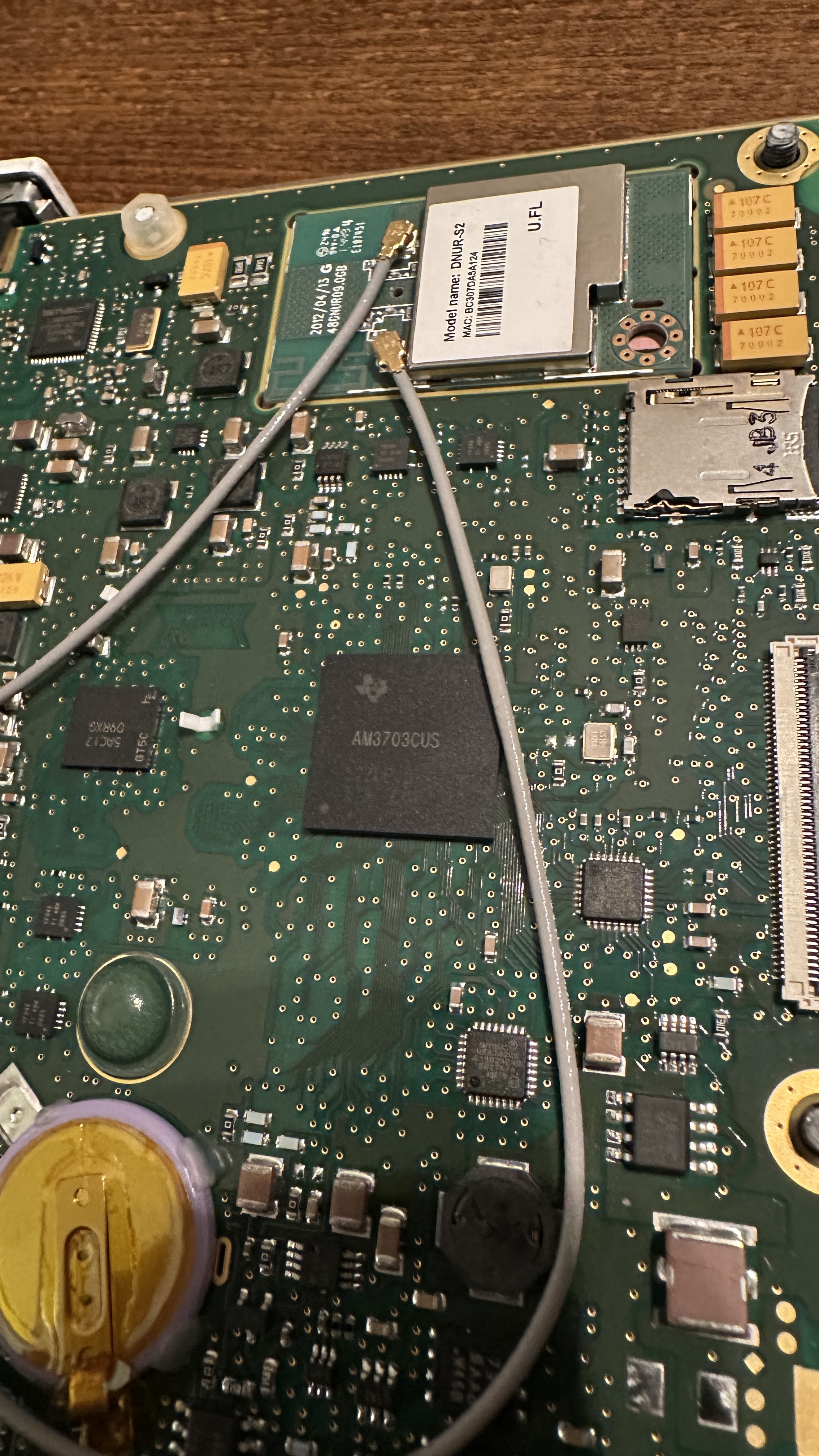
The theory of operation is quite "simple", you can think of the detector as a huge CCD array with columns and rows which are scanned by an FPGA. For processing and communication the detector is equipped with an AM3707CUS ARM-8 SoC. And to my surprise there was no eMMC or soldered flash on the pcb but a micro-sd card! Wow, might be my lucky day!
After removing the sd card, my first step was making a backup of the card. I was afraid it could only contain buffered images while waiting for the availability of a DICOM server but the first peek at the data on the card was promising!
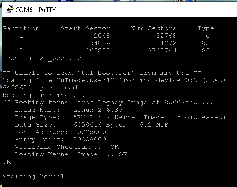
There are three partitions on this card:
Partition 1: FAT16 filesystem containing "MLO" and "uBoot.bin".
Quick research reveals MLO is the initial loader which is accessed by the booting AM3707. This loader then starts uBoot.bin. Now we're in the usual linux boot realm!
Partition 2: Ext filesystem containing "uImage.factory" and "uImage.user1"
Each file is approximately 6.5 MB in size, more on these later!
Partition 3: Ext filesystem containing the folder "userFiles" and "customersFiles_part.ext2"
The userFiles folder contains the main configuration files for the wifi access point, detector and network settings.
The customersFiles_part.ext2 image file is mounted at runtime and serves as non-volatile user data storage for acquired images.
Hmm, all in all interesting but at first glance there seems to be no place where a custom application controlling the detector, loading the fpga and so on seems to live. Maybe everything is controlled from the software package running on a host computer? At least the available manuals for the detector seem to suggest that a standalone operation should be possible, so let's dig deeper.
My next two goals were trying to gain access to the serial console (every linux based system has one!) and looking at more detail into the files on partition 2 which are uImage.factory and uImage.user1 as they have rather promising filenames!
The Serial console
Have you ever seen an embedded linux based system without a serial console? Me neither! Assuming it hasn't been disabled (and as the detector is well enclosed and its internals are normally way out of reach from the curious tinkerer) I hoped for the best.
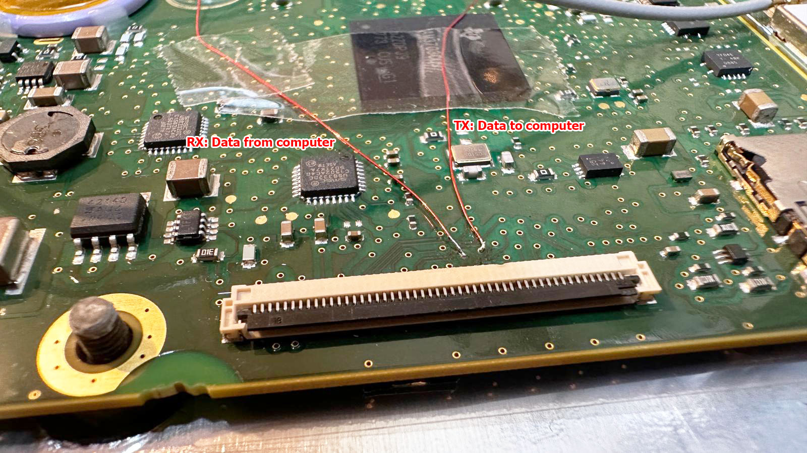
The pcb contains two big flat flex connectors, one near the SoC and anoter one on the other end of the circuit board.
Using an oscilloscope, I started probing on the connector in close proximity to the SoC. Probing each pin while connecting the battery and waiting a couple seconds, it didn't take long to find the right one. I started with capturing the whole boot process to a file for later examination. But it would be nice to interact with the system, so let's hunt for the receive data pin. As a hardware and software engineer myself, I usually route both pins next to each other. So let's try to solder a patch wire to the surrounding pins and throw some chars at it. I should have played the lottery this day as the first pin I tried was the right one! No password prompt and full access to the shell, that's a major breakthrough!
The next step will be a custom breakout board with a 50pin flat flex connector to make probing the connectors easier and more reliable compared to soldering wires to vias on the pcb.
Dissecting the firmware: uImage.*
As I didn't want to mess any more with the hardware for now, I started with analyzing the firmware.
Running binwalk on uImage.user1 reveals the following:
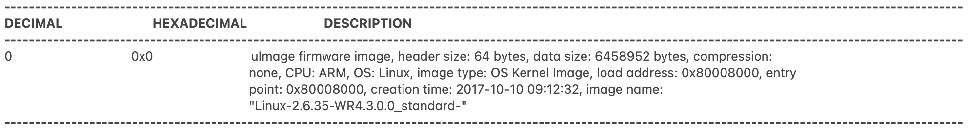
Hmm, nothing too surprising, to be honest I expected to see more... but from prior experience I know that binwalk is sometimes a bit picky once it has detected a valid header so let's strip the first 64 bytes (the uBoot header) from the file and try again:
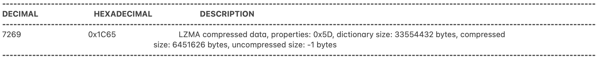
Aah, now we're talking! I knew there must be more!
My best guess for now is that the 7k stub in front of the LZMA archive has to be the decompressor binary as this functionality wouldn't fit within the uBoot loader itself.
So let's try binwalk -e to extract the LZMA archive at offset 0x1C65 which results in a new file, let's call it decompressed.bin.
Using binwalk again on this file reveals
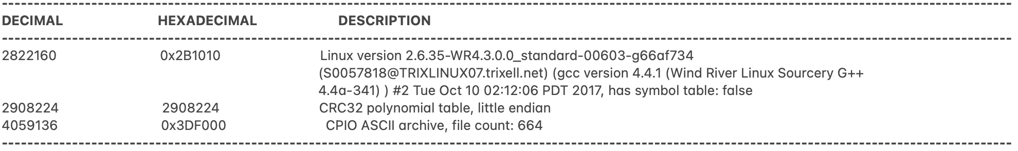
We're one step closer to the initramfs! The area from 0x0 to 0x3DF000 contains the kernel while the initramfs is packed into a CPIO archive starting at 0x3DF000. After chopping the file apart at this offset and extracting the CPIO archive using binwalk -e again, I am greeted by the main file system including all the Trixell specific binaries including the main binary "Portable2App". Yeah, quite a breakthrough!
To summarize our discoveries, let's draw a memory map showing what goes where:
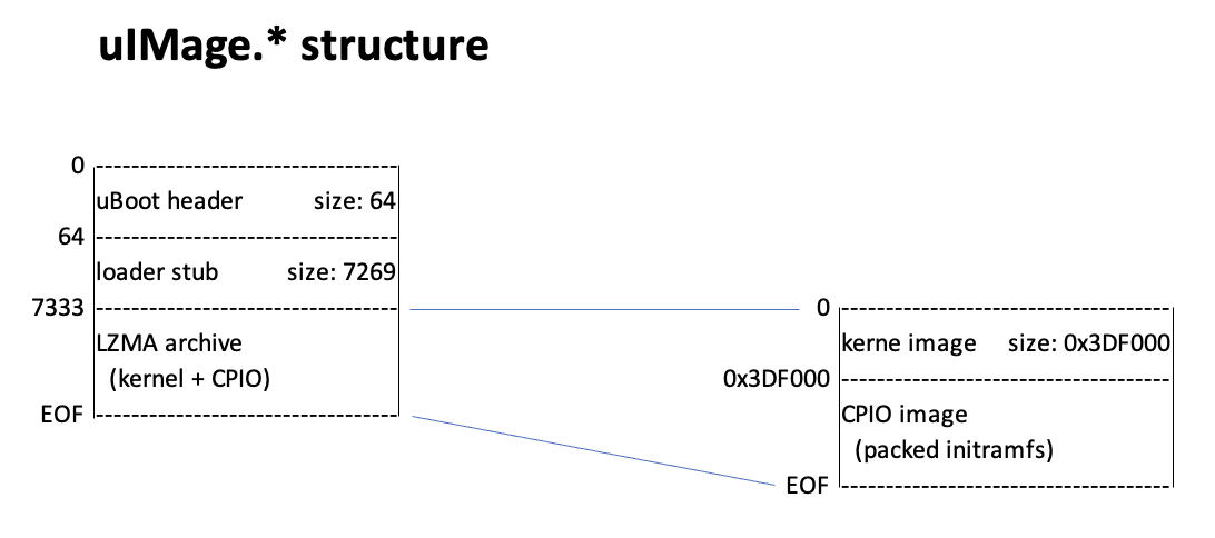
I'm a bit disappointed as there is just this one big binary with approximately 2.8 MB and it doesn't appear to be controllable via the command line as I was hoping for. Hmm... it seems more work is required.
At least now I have most of the tools to replace the ssh password hash in the shadow file with my own hash which will allow me to connect as root via ssh. "Just" repack the modified CPIO archive, append it to the kernel, LZMA compress everything, add the 7k loader stub, run mkimage to generate a new, valid uBoot image, copy it to the sd card and hope for the best :-)
But let's start slow and start with repacking the original files without any further modifications.
Repacking the kernel image
Well, let's give it a shot! First I repack the initramfs into the cpio archive, append it to the kernel image, LZMA compress the whole thing, copy the loader stub in front of the file and run mkimage to rebuild the uBoot header. After messing with my macbook to get write access to the ext2 partition (what took longer than dissecting the firmware...) I have a copy of my "uImage.new" on the card and attempt the first boot.
I have to admit I'm quite excited but it goes as feared, my image passes checksum validation but it is stuck at "starting kernel...".
After messing around a bit, my best guess is that the loader stub has issues with the different size of my compressed LZMA image or does some checksum checks on the file which would, of course, fail after recompressing it.
To get a clue on what is going on, I start by extracting the loaders from uImage.user1 and uImage.factory. Comparing them, there appear to be only a handful differences between the files. I start by generating different CRC checksums over the LZMA archive and searching for them in the loader binary which leads to no result. Next step is searching for the size of the LZMA archive and this seems to be hardcoded in the loader binary in several places, either directly or with an offset of a couple bytes. As I'm in the process of pivoting more and more towards Python for my software engineering day job, I start building a Python tool which accepts a LZMA image as input data, computes its size and patches the loader binary. I have to admit, Python gets more and more handy for stuff like that! Unfortunately, the first boot attempt with my patched loader ends in starting kernel..." so more investigation is required.
The configuration files
Looking through the third partition I stumbled upon the folder "userFiles" containing a couple files:
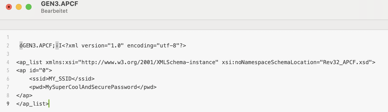
GEN3.APCF : WiFi settings (AP SSID & password)
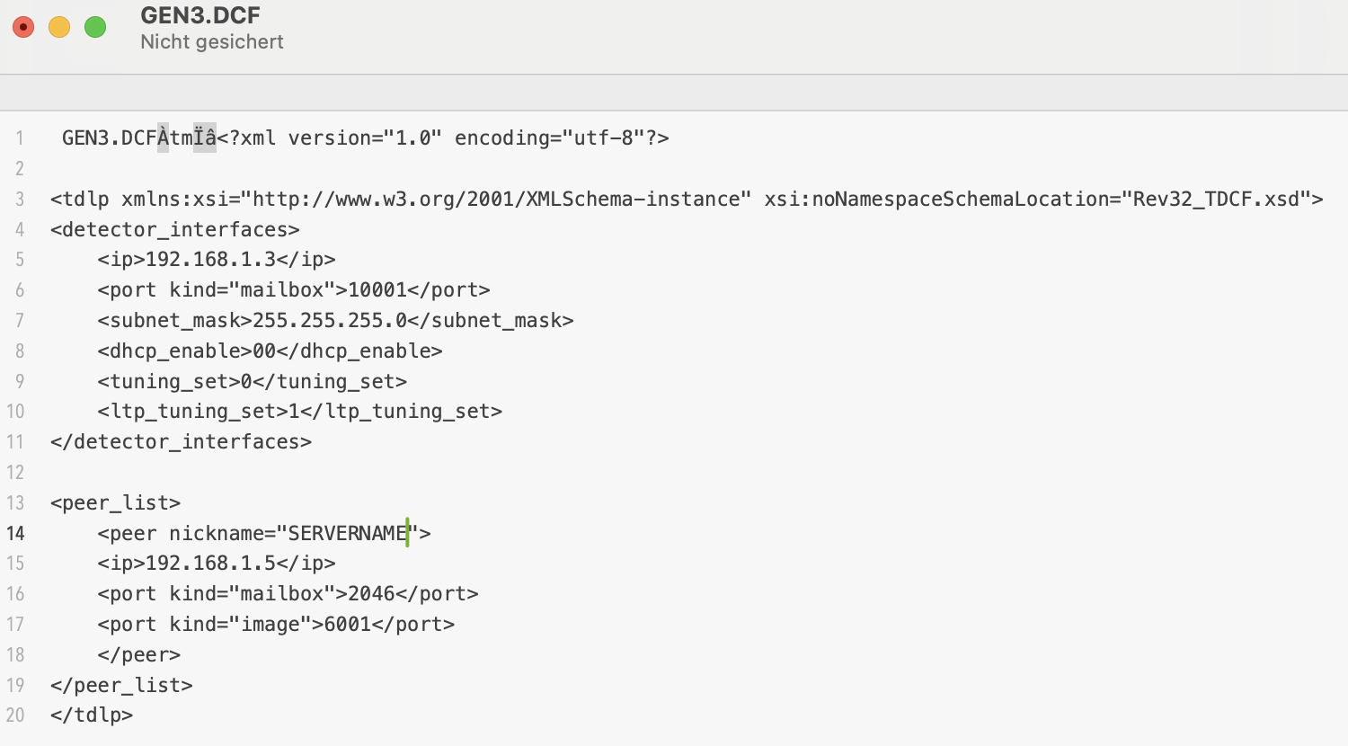
GEN3.DCF : network parameters (ip address, mailbox config ports, dicom ports, ...)
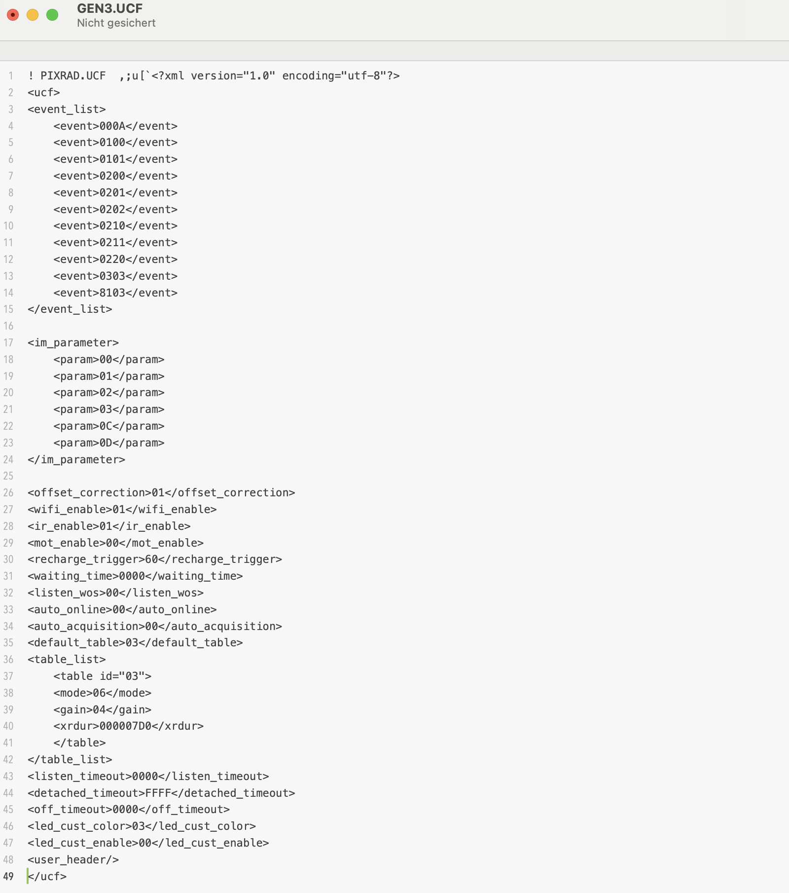
GEN3.UCF : detector settings (acquisition mode, WiFi enable, gain, exposure, ...)
And again, at first glance this looks too easy and as a first approach I replace the SSID and password in the APCF file and change the ip configuration in the DCF file. A reboot later I check the setings with ifconfig and I sadly realize that the firmware has fallen back to some default settings instead of my beautifully formatted xml style file parameters. What a pity! After some tinkering the weird nonprintable characters at the beginning of each file catch my attention. What if Trixell tried to ensure configuration file integrity by adding a checksum at each file header? Fortunately the files are short and easy to work with. I start by analyzing the two shortest ones and soon realize that two bytes encode the total file size. Another byte seems to be some kind of checksum. Personally, when deciding to use an 8bit checksum, I would use an XOR over the whole document with the size bytes and initial checksum value being set to zero (as both size and checksum are computed in one step when saving the document). This is just an educated guess but calculating the checksum this way I obtain exactly the values which are stored in the files!
A couple minutes later I have implemented a small python tool which accepts the config files, recalculates size and checksum values and saves the modified files. And another reboot of the detector later, a new device has successfully joined my wireless home network :-)
The UCF file is another can of worms and it occurs to me that this file might be the key to autonomous operation of the detector.
Looking through the initramfs files, I found another UCF file with some factory default parameters and I realize that there have to be way more parameters than used in these files. This is the moment I start Ghidra and start decompiling the Portable2App. Not to break or circumvent anything but to search for the huge if/else struct which is required to implement the parsing of the xml style config files. I would assume lots of nested strcmp functions:
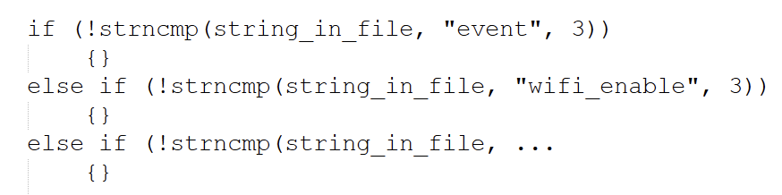
Additionally, I know a few of the strings to look for from reading through the config files I have found on the sd card so far. One evening later I hit the parts of the firmware which are responsible for file parsing. These sections also do some rudimentary plausibility checks which give me hints on the accepted values. This unveils a whole lot more commands! In terms of supported values, I have to take some vague guesses but at least this is a good starting point for further experiments.
The computer side of things: TDLP
Although I would be absolutely happy with a detector running in headless mode, being able to change parameters on the fly would be nice. I know that Pixrad supports setting acquisition parameters and starting the image capture. The proprietary protocol used by Trixell is called "TDLP", maybe an acronym for "Trixell Detector Link Protocol"? I can't find any protocol descriptions or pcap captures online, that's why I revert back to Ghidra again. From the config files I know that there seems to be a "mailbox" system which is used to exchange (control) messages between the detector and the digital radiography software. Listing the open ethernet ports with netstat reveals the DCF file's mailbox receive port to be a UDP socket where the detector listens for messages. I wouldn't have guessed they use UDP, I would have searched for TCP sockets and wasted some time... My next step is to look for ethernet related functions and especially UDP RX related code. These vtable calls in the firmware are a pain in the butt to follow! Plain C is way easier to decompile and get along with compared to C++ binaries... I'm running in circles and I reach lots of dead ends but sooner or later I reach a function which tests whether the incoming data packet starts with the string "mbox". The evil thing is that they don't do a string compare with the word but the 32bit literal consisting of the ascii values of these four letters. Or at least that is what the compiler optimisation made of their string comparison :-)
Reading through more functions in the same area of the code seems to suggest that the packet is formed of the "mbox" keyword followed by some type of version (2 bytes?), parameters (2 bytes?) and data (2 bytes?). Oh man, this would be so much easier with a simple capture of a few commands in a working system!
I'm pretty sure this format is neither complete nor correct but nonetheless I try to just throw some "mbox" messages at the udp port. And the detector.... does absolutely nothing. No reaction at all. Argh, not what I was hoping for! This whole firmware is full of debug text but there is no output to the console or dmesg.
In an attempt of desparation I start at the entry point and what I identifieed as "main" function. Here happens some initialization stuff with debug messages like "init detector", "init panel", ... Why can't I see them anywhere? Following the debug function reveals two things:
The debug output depends on the start arguments when opening Portable2App
The debug output depends on a comparison with byte 13 in a weird array whose origins are hard to grasp.
Let's do the easy test first: kill the application and call it with parameter 1 or 2. But no cigar yet, absolutely no output. So let's pivot to this check whether byte 13 is zero (skip debug output and just waste some time in a loop) or non-zero (process debug string).
As I am losing my patience, it is time to tackle the firmware with the sledge hammer: the comparison is realized with a "branch if zero " opcode in the assembler listing. Googling for an ARM8 opcode list reveals that the "branch if not zero" instruction is the same length. I open the binary in a hex editor, patch the opcode, copy the file to the sd card and give it a try. Et voil�, at least some debug output, although you can't use the word "verbose" in one sentence with this debug output. Literally a few messages at startup, that's all. Maybe there are different log levels and I'm in the least verbose one by default? Time to diverge to another route again...
One clue might be in the UCF config files as my analysis of the xml parser showed the presence of a "debug" command, maybe I have just reached another dead end and have to proceed there...
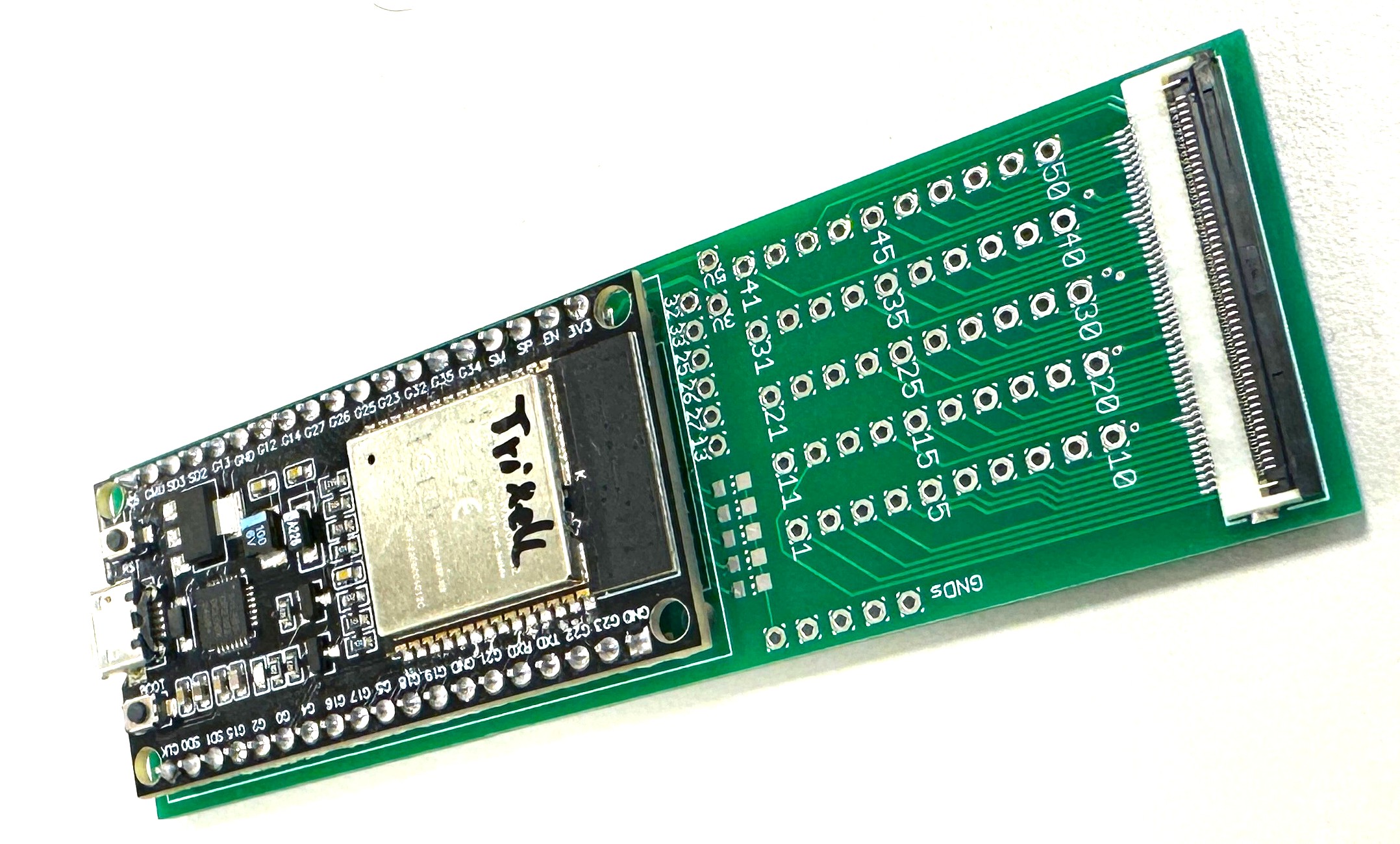
Update: 03 / 2026
Good news! The FFC breakout boards finally arrived! Now I can probe the 50pin flat flex connector signals WAY more convenient! Every pin is routed
to a solder point. On top of that, I added an ESP32 with a couple I/O's and LEDs to the board. By adding jumper wires I can connect the ESP to the
FFC pins.
Two of the ESP's pins will be connected to the serial console of the Trixell panel. Upon boot, the firmware detects, when the OS is up and starts to inject my own certificate to
the list of allowed SSH clients, thus enabling me to connect via ssh without having to mess with the whole LZMA compression + bootloader decompressor stage for now. On top of that
I forward the serial data to a TCP socket for remote console access what makes tinkering a lot easier!
(c) DJ9KW