
When cleaning up my old room in my parents house I discovered a pile of compact cassettes, most recorded by younger me three decades ago. Hesitating between tossing them out and keeping them, I felt some kind of nostalgia and decided to keep them. This leads to a new problem: not owning a tape deck anymore. And because I like the style of bouncy needles and black anodized aluminium (and watching a couple of Techmoan's videos on youtube) the choice was already clear: it had to be a Sony TC-D5M. Although there are more recent versions of this machine, the TC-D5ProII, this model has XLR microphone inputs and omitted the RCA-jacks for line level input and output which makes it less attractive as a home use player and recorder. So let the hunt begin, it was harder than expected to catch a decent specimen on eBay and the german platform "Kleinanzeigen" (facebook marketplace equivalent) for a reasonable price but in the end I managed to get not one but two machines, one in rather good physical shape but with some electronics issues, one looking like it had a rather hard life but working fine. Both in total a lot cheaper than the "overhauled" snake oil models offered allover the internet...
Initially I intended swapping the big control pcb between the units but once I saw the gazillion thin wires going to both sides of the board (connectors are evil, only directly solder everything to the pcb!) my motivation vanished. Well, I guess a repair might be easier than swapping the pcb...
All of the following is valid for every version of the recorder: The Sony TC-D5, the TC-D5M, the TC-D5pro and the TC-D5proII.
Unit 1 : motor not spinning at all
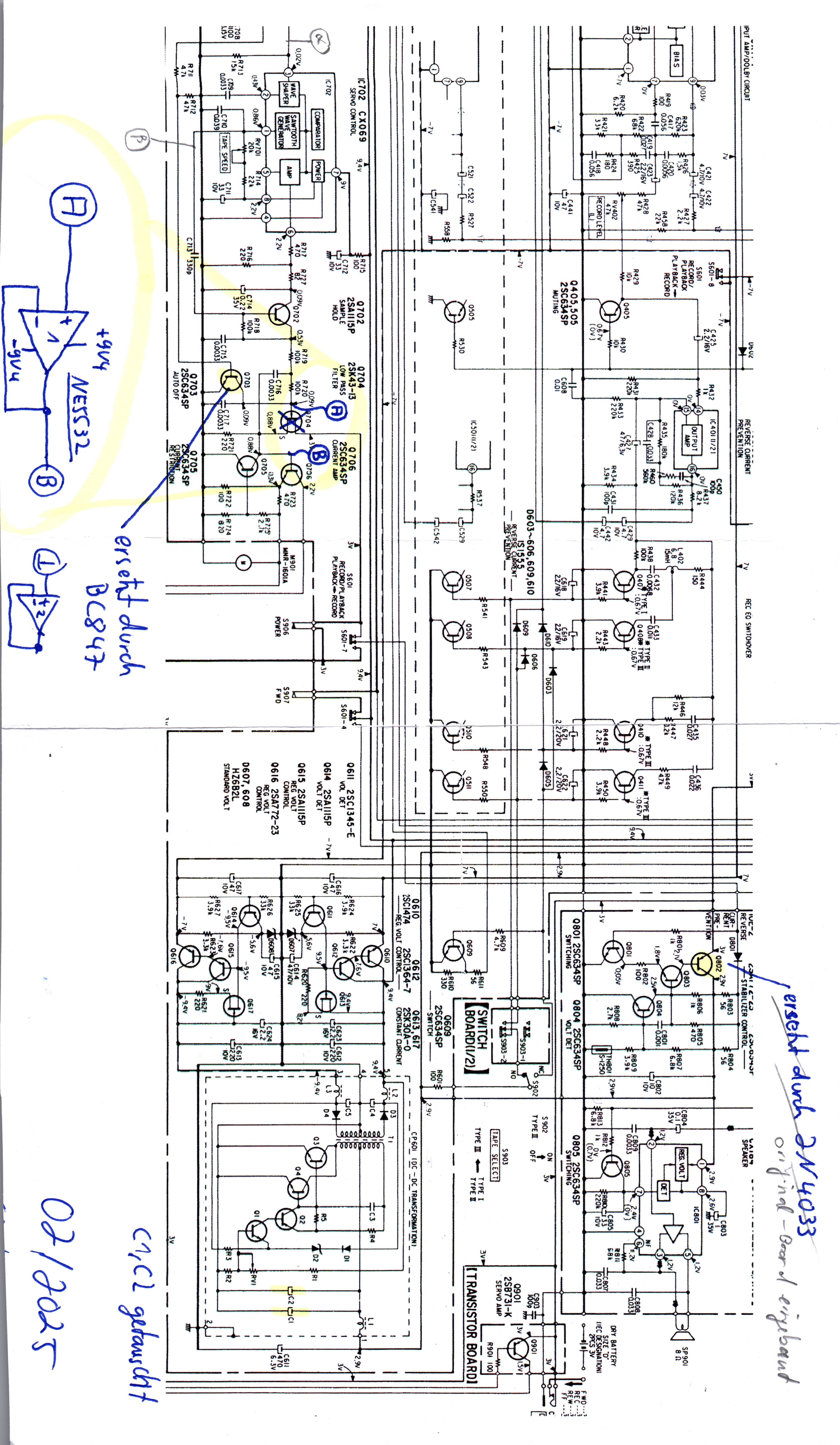
This is the nicer looking unit. No movement at all when pressing play, ff, rew. Ha, easy fix, it must be the DC/DC-converter stepping up the 3V from the batteries to +/- 9 volts! At least that is what many others throughout the internet discovered. And for sure, there is no output on my converter, too. But there is also no voltage reaching the input of my DC/DC-converter! Just staring at the boards (yes, staring is one of the most powerful debug tools!) I find a suspect: Q802 is blown in half. I don't have the proper replacement part but a 2N4033 from the parts drawer should work well enough.
With Q802 replaced I can measure 3 volts at the input of the DC/DC-converter but still no output.
So I remove the converter from the pcb, desolder the metal lid from its base and replace the electrolytics (sorry, I totally forgot to take any pictures during this surgery...). Long story short, the converter is back to life but the motor is still dead. Bummer!
So it is time to switch to a more methodical approach and powering up the oscilloscope to take a look at the servo control integrated circuit, s Sony CX069. Good luck finding any information on this one, not even think about a datasheet. No chance! Well, I have the not-so-nice unit, which works, so I can at least compare between both of them. Let's hope for the best, some people suggest that accidentally using a power supply connector with center positive instantly fries the CX069...
Apparently all signals on the input side of the control ic look fine, when I turn the reels and the motor I can see pulses. The output of IC 702 (pin 6) is stuck at +5V (way higher than the annotation in the schematic suggests, plausible as the motor is not turning and the loop output is saturated at the upper end.). The output is switched by Q702 which is used as a sample-and-hold gate and then low pass filtered by R719, R720 and C716. JFET Q704 buffers this high impedance signal, Q706 drives the power transistor. Q705 serves as overcurrent protection, in the case of excessive draw from the motor its base voltage rises above its threshold and it starts pulling down the base of Q706. All in all quite straightforward... The question is: why doesn't the +5V on pin 6 make Q704 conduct some current? I start by replacing the sampling gate Q702 and the JFET with some generic type although I'm pretty sure its threshold voltage might be critical. After many attempts (and working on the unit is a mess as there is a ton of thin wires going everywhere and you're afraid all the time that anyone gets loose and you'll never find out where it went...).
In a nutshell, I lose my patience and decide to throw out this ancient JFET. All it does is convert a high impedance source into a low impedance drive signal, something every modern opamp can do quite well! Just out of curiosity I tack in a NE5532 set to unity gain, which works absolutely fine!
Makeshift solutions tend to last the longest, that's why I just cover the opamp with some Kapton tape. Repair done, mission accomplished!
Unit 2 : takeup reel torque too low
At first glance this unit appears to be technically in good shape but once I start using it a bit more, there is one issue with some tapes: the takeup reel torque is really low. On a couple tapes it isn't strong enough and the takeup reel stalls. At first I was thinking this is due to some deteriorated belts but then I found a great forum thread showing how to adjust the torque of the takeup reel's slip clutch by shortening a spring by three turns. This approach proved to be a success!
The spring is quite easy to reach from the top of the machine. The first step to get access to the spring is to remove the top cover of the unit, including the tape lid. Then, remove the metal plate on top of the mechanism:

This reveals the mechanism including the spring which engages the slip-clutch:


Removing the spring can be a bit tricky but using tweezers in one hand and an exacto-knife in the other hand it was quite easy. I had to shorten the spring by removing three turns. I've done that by forcing the blade of the exacto knife in between the spring turns and using it as a hard surface to bend the spring by 90 degrees. I used side clippers to remove the excess spring material. Reinstalling was done the same way as removing the spring with tweezers and the exacto knife as a pointy tool.
After reassembling the machine the final result using an old torque meter test tape:

I would call this a success, before restoration, the indicator was showing zero, now it shows round about 5. The torque meter cassette certainly is out of calibration but it is still working great for comparative measurements.
--- WORK IN PROGRESS, TO BE CONTINUED... ---
(c) DJ9KW
PREV: A DIY HP diode detector power sensor substitute and a 11730A sensor cable
OVERVIEW
NEXT: A reverse engineering deep dive into a Trixell Pixium 3543ez x-ray detector panel