
To be fair, this project was hugely inspired by the work done by Daniel Tufvesson (SM0XGY), the author on waveguide.se. Without his work I might not have started this attempt in building a cheap, modest power sensor for my 435A and 436A. So all credit belongs to him,
visit his great documentation and journey to build a decent HP compatible diode detector.
I really like my 8481A and 8484A power sensors. Originally paired wit two 435As I uprgaded the readout unit to a 436A (and I still search for a 438A...) so I had a 435A left lying around. I planned on selling the device but soon discovered that the money I could make by selling an old 435A wasn't worth the hassle of packing and shipping. So with a spare power meter available I soon started to look for ways to repurpose it, ideally by building my own compatible DIY power sensor, considering the prices of used working ones!
This is when I discovered Daniel's webpage. I decided to give his design a try but I wanted to change a couple things. First, I decided against his approach of separating the detector head from the amplifier circuit, instead I tried to minimize the board area (and thus capacitance) of the realizted circuit parts. My second change is the chopping JFETs. While Daniel uses two discrete parts which need to be a matched pair and should be kept at the same temperature, I opted for a dual JFET in a SMD package I already used with success in another project, the LS844. It's still being manufactured and its data should match the power sensor quite well.
Let's start with the easy things first, without a proper cable there's no way to test the DIY sensor head !
Luckily I have access to the original HP 11730A power sensor cable, so it was a quick task to find out which pins are used and there are still some matching connectors and receptables in an old drawer in the office, perfect!
I've attached a picture of my lab notes below, although the notes are in German I presume it is rather self-explanatory.
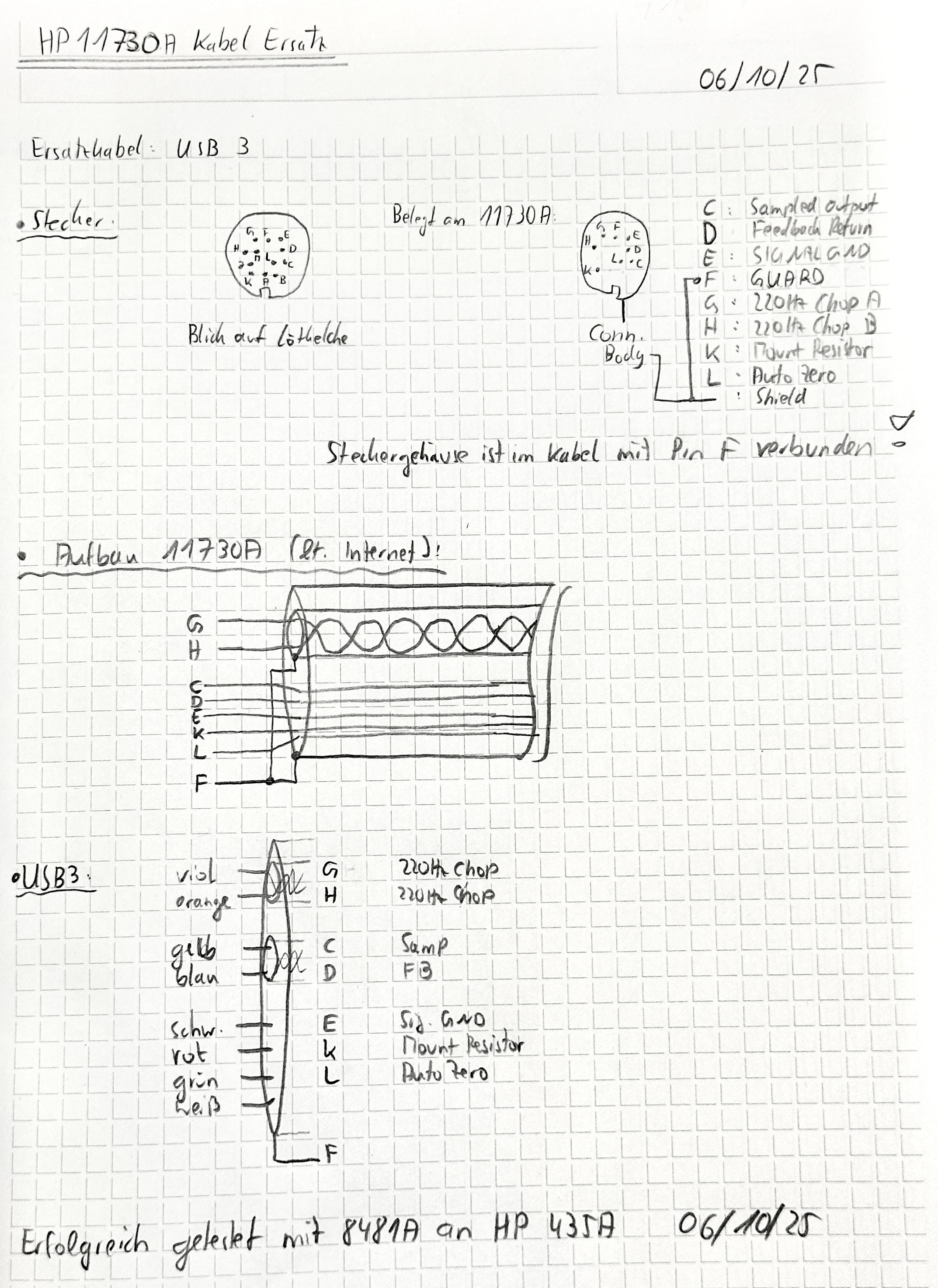
My notes while deciphering the pinout of the original cable
The important thing is that the two 220Hz choppped gate driver signals (pins G and H) have to be shielded in order to avoid crosstalk with the sensor head signals.
The best option in terms of the cable was to use an USB3 cable. I took one out of my cable drawer and chopped off both ends.
The two chopper signals use one of the shielded twisted USB3 pairs, sampling output and feedback return use the other shielded USB3 pair.
Now there are only three wires left: signal ground, auto zero and mount resistor, these use the USB2 wires.
After assembling the connectors and mounting their clampshells and housing I tested the cable using an old HP 435A power meter and a known good 8481A power sensor and it works just as good as the original HP 11730A!
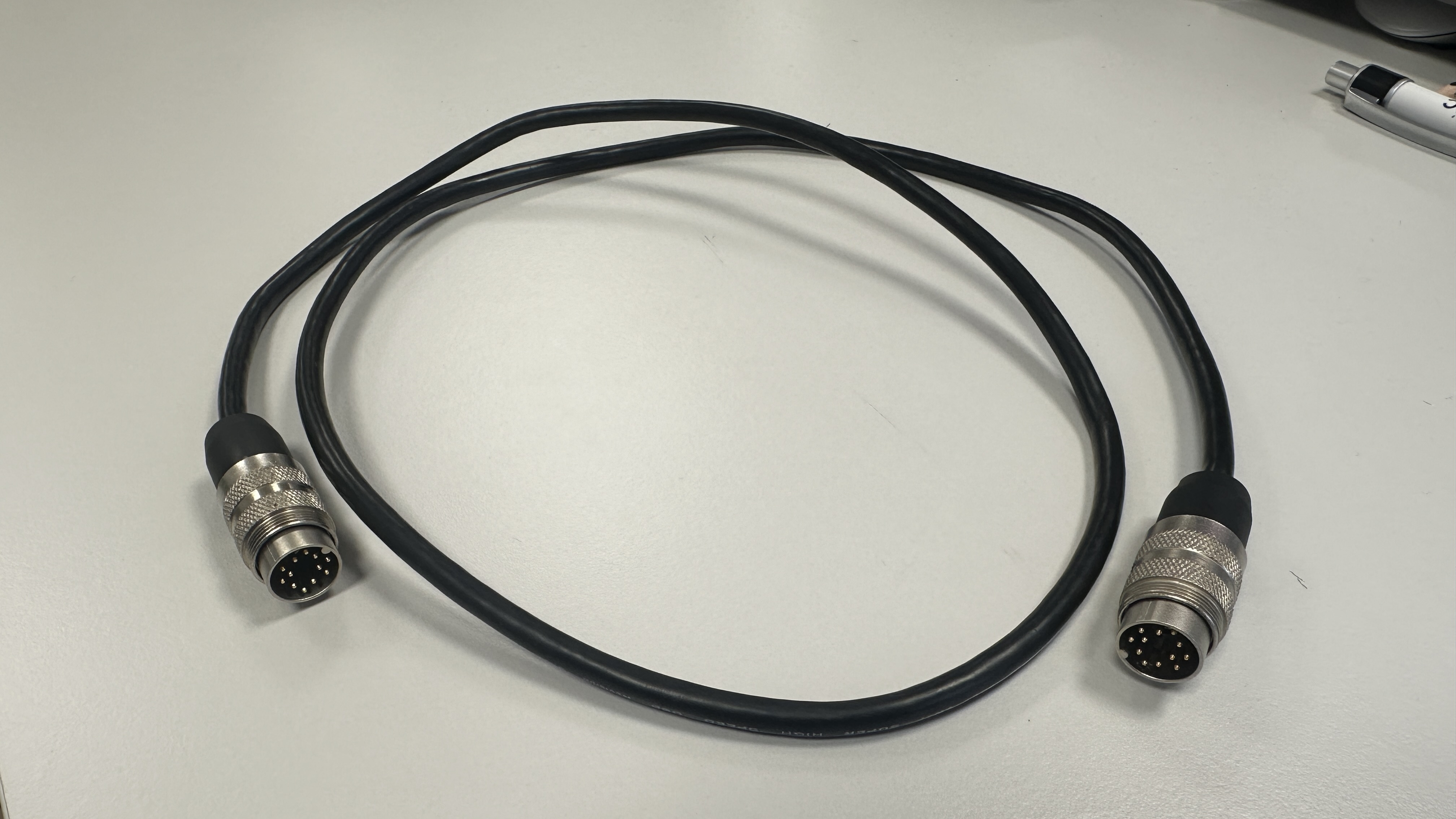
My finished DIY 11730A
Regarding the sensor head, I came up with the following schematic and pcb:
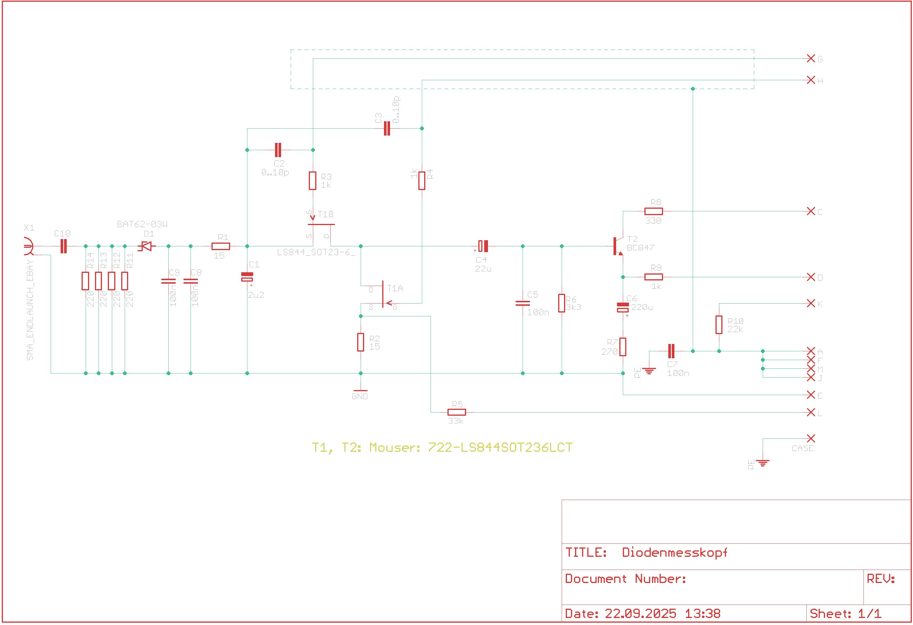
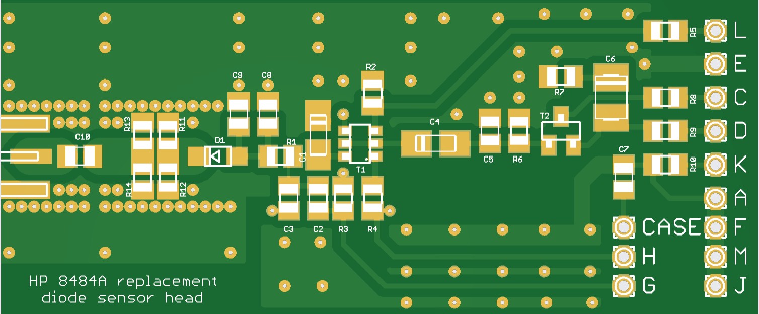
The similarity to Daniel's design is obvious but I expect it to be less critical in terms of temperature stability due to the dual JFET.
--- WORK IN PROGRESS, TO BE CONTINUED... ---
(c) DJ9KW, 09/2025
PREV: A standalone Dolby S En-/Decoder
OVERVIEW
NEXT: Sony TC-D5M overhaul and repair