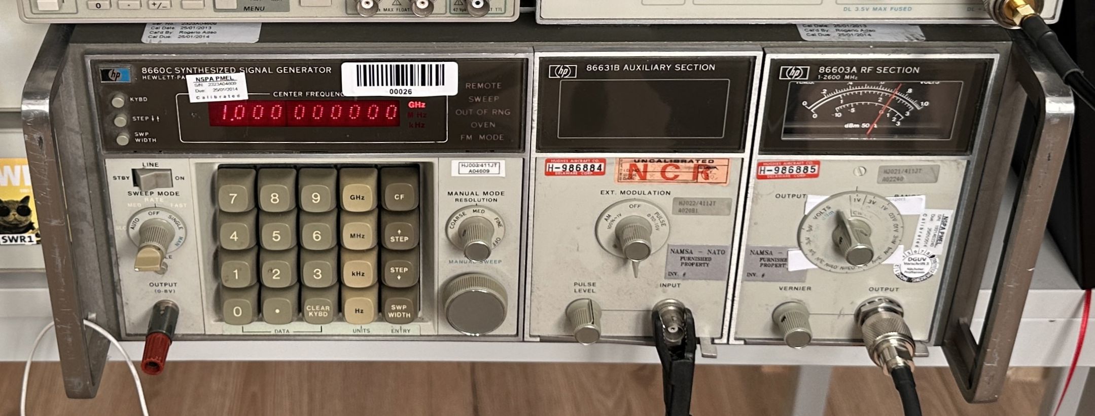
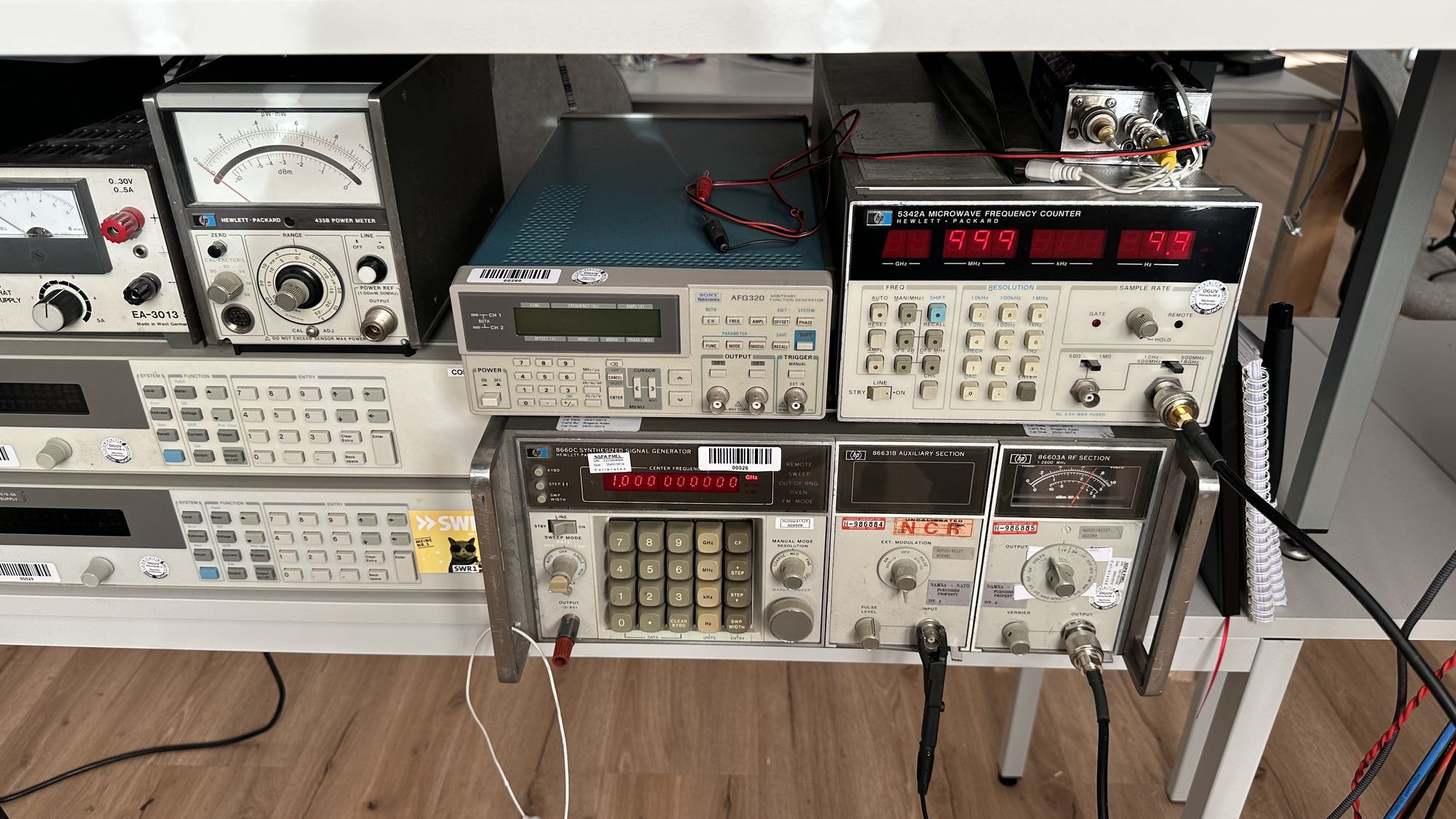
Another story starting on eBay a couple years ago. One day I spotted this boat anchor, a HP 8660C synthesized signal generator up to 2.6 GHz. The unit was sold as non working and (probably due to its size, weight and age) was quite cheap. So I made an offer and to my surprise, it was accepted. I guess someone was happy the thing had gone at least :-)
Upon arrival, the unit showed quite some battle marks, lots of dirt and many stickers showing its history. Seems this unit went through quite a lot of hands in its former life!
Expecting a challenging repair, I turned the unit on. Yeah, it powers up, shows signs of life and no magic smoke, a good start! But the output is all over the place. Hmm, on the back there is a switch to select between internal and external reference and it's set to external. So I powered the unit off, switched it to internal and powered it back on. Et voilà, the signal generator is back to live! I guess the seller just didn't check (or had no clue about the thing...). But during the first performance tests it got apparent that there were some issues with the output attenuator making intermittent contact. Sometimes, you changed attenuation and the output dropped to almost zero, other times it worked just fine. So it was time to remove the attenuator from the RF module, disassemble and clean it. And this is when things went sideways, I removed the attenuator, stored the signal generator underneath my desk in the office and forgot about the it for the next few years. A couple cardboard boxes and other electronic stuff stored in front of it did its best to hide it from my eyes. But these days the company decided to move to a new building, thus the unit had to be moved, too. This left me with a couple choices, number one: Sell the unit as defective or repaired (Uh, I really have no motivation to do the packing so it survives shipment). Option two: Take it home and store it there for the next couple years (Uh, way too big for my taste!) and at least option three: repair it and add it to my new lab space beneath my desk. Considering the amount of handling the unit required to reach each of these goals, I opted for number three :-)
Fixing the attenuator was quite straight forward, applying some Deoxit (or the german equivalent, Kontakt 60) to the contacts and bending the dc connecting springs on the coils back to their original shape.
After highly motivated reassembly (of course with all lids closed and all screws in, as I was expecting everything to work just fine now) the attenuator was doing absolutely nothing when I turned the dial controlling the attenuator. Hmm, I'm quite sure, this worked the first time I powered it up when I got the unit. As I was somewhat lazy when removing the attenuator from the unit, I didn't even bother to insulate the desoldered wires which drive the attenuator coils. My best guess is that one or more of these wires must have touched the grounded case when I did a quick test run of the unit. Bummer, quick and easy fix turns into a
Curious Marc Style low level board repair.
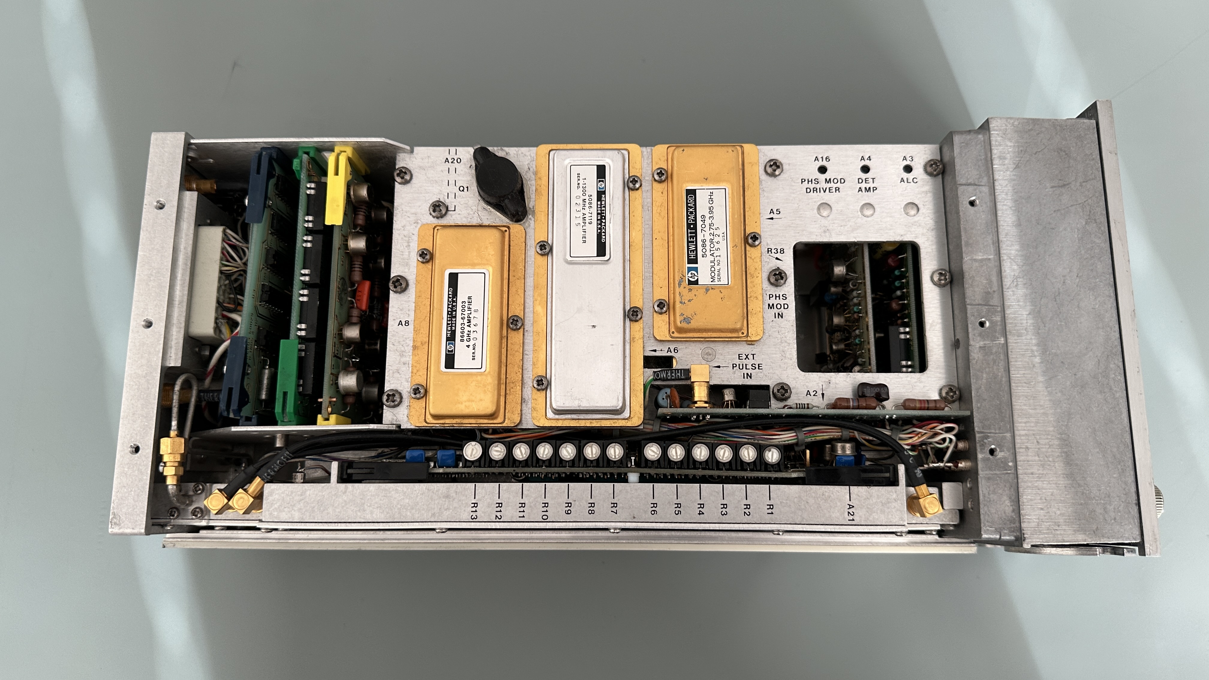
Peeking through the service manual reveals the drivers for the coils are located on a separate board. On one hand these submodules make rework a lot easier but on the other side probing the circuit without the proper riser cards is a pain!
The card with the yellow tab is the attenuator coil driver board
There are different revisions of the driver board and I seem to have the older one. This version has no overcurrent protection which was added in the newer release. Maybe this would have saved me from having to repair it? We'll never know!
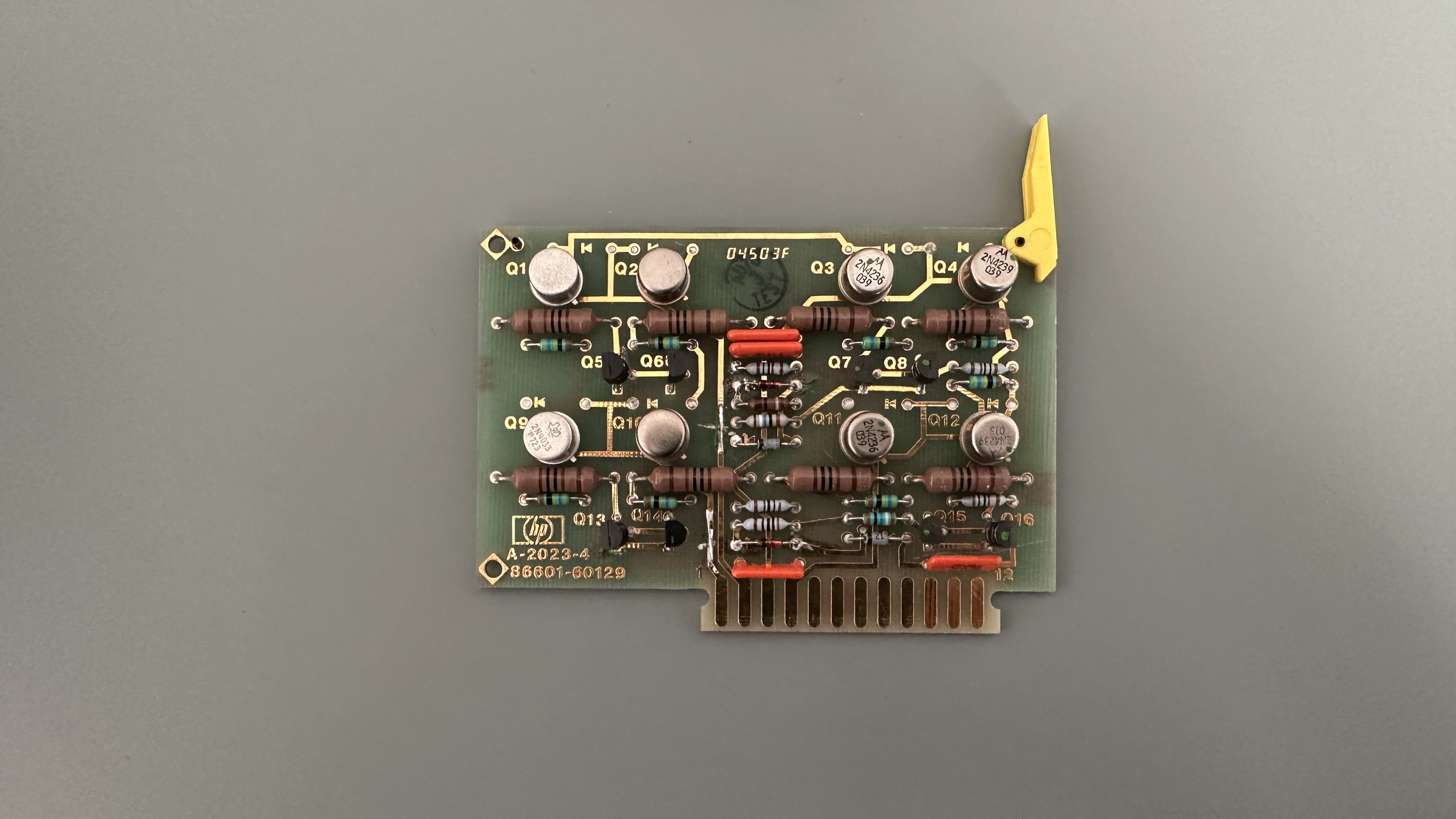
The card with the yellow tab is the attenuator coil driver board
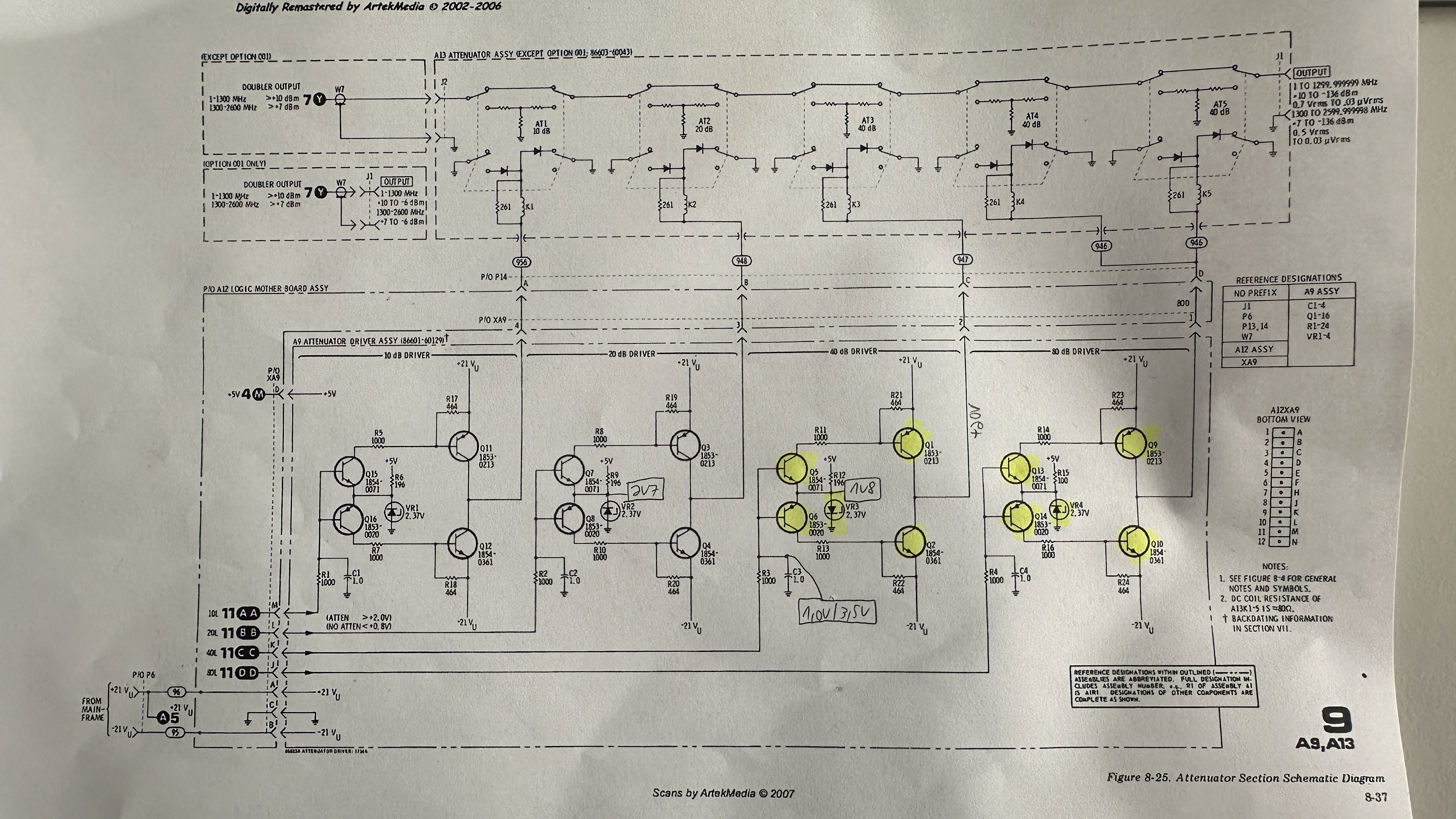
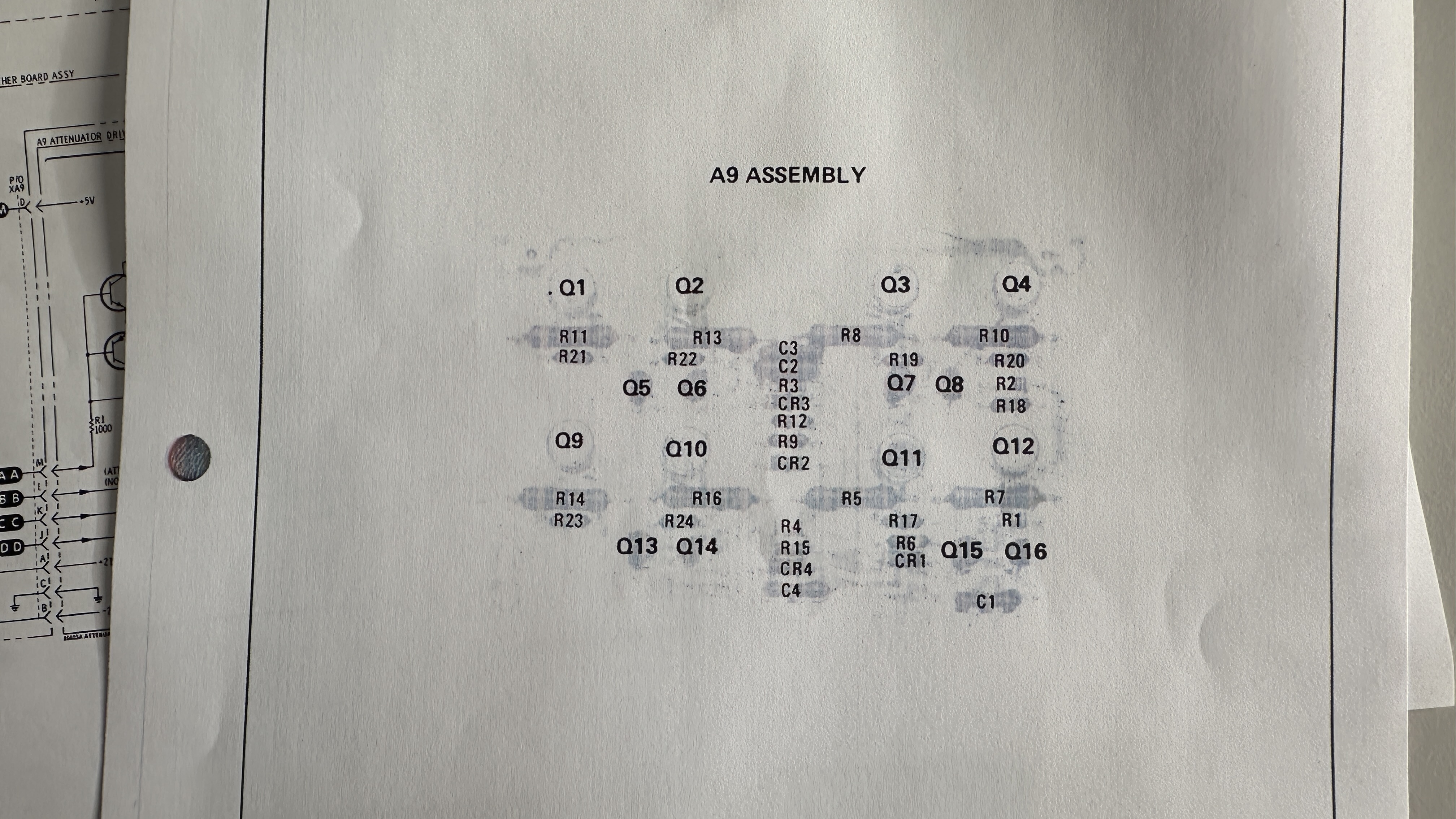
The schematic of my older style board; yellow markings are the parts which needed to be replaced
As a first step, I connected a lead to the +20V power rail on the board, reinstalled the driver card and measured the supply voltage. As no coil reacts when changing attenuation levels, I assume that something in the power bath is blown. The measurement reveals that the +20V doesn't make it to the driver board while I can still measure them on a test pin on the backplane where the driver board is plugged into. As removing the backplane would require to disassemble half of the module, I opted for a bodge wire connecting the +20V test point to the connector which should have +20V applied. At least for a quick test...
And this proves to be the culprit, somewhere buried between many wires and boards, an emc choke on the backplane went open, probably due to overcurrent. I could replace it but I can live very well with my bodge wire and decided to leave the unit like this.
The attenuator consists of 4 sections: 2x40dB which are driven together to form a 80dB attenuator pad, a 40dB stage, 20 dB and 10dB. Measuring the output levels showed that two of the stages (80dB and 40dB) are stuck, once active they can't be disabled anymore, so I attached another four wires for measurements: to the digital logic level inputs of the driver stage and to the outputs. While the inputs changed between 1V and 3V, the outputs of the non-working stages were stuck at +20V all the time.
Measuring the zener reference diodes showed implausible readings so I swapped them for new ones, which didn't fix the issue. Next approach was removing the differential amplifier transistors. One of them measured shorted between all pins and after replacing both and powering up the unit, one of the diff amps and the zener releasd their magic smoke. This reminds me of the days repairing audio amplifiers with all their DC-coupled stages. If you missed one bad transistor, all of them tended to blow up upon power on. Same here, more measurements revealed that one of the output transistors is also shorted. Without further ado I decided to remove both output and diff amp transistors and the zener and replace all of them. It's my lucky day, in my parts drawer I found some perfectly matching output complementary transistors, also in a metal can package. 60V, 0.8A seems to be just right. The diff amp transistors got replaced by BC547 and BC557 respectively. I didn't even look them up in a cross reference list for these weird HP numbers as gain and bandwidth aren't critical at all.
After swapping and bench testing the board works fine and now I can switch between output levels without any problems. Unit fixed! Now I have an additional signal generator at my bench, fully working.
(c) DJ9KW, 09/2025
PREV: HP 5342A power supply issues
OVERVIEW
NEXT: A standalone Dolby S En-/Decoder