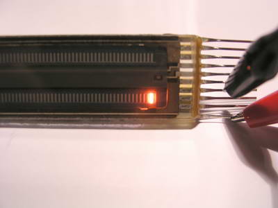
View of the IN-33 reset segment powered up
Plasma - Bargraph with IN-33 "glow transfer" - tube
A few years ago I ordered some pieces of nice-looking
IN-33 plasma glow transfer bargraph tubes:
View of the IN-33 reset segment powered up
At this time I didn't know a lot about these tubes, I only
knew the peakmeters manufactured by RTW which are very common in the professional
studio electronics, e.g. radio stations.
When the tubes arrived, there was a datasheet
of a similar tube included which showed me that it wouldn't be so easy to control
them.
Unlike linear-driven IN-13 tubes, the IN-33 is a tube which consists of a 3-phase
segment drive which was originally generated by a euro-card-size pcb full of
ttl - ic's (74HCxx) and comparators. This seemed to be much to extensive so
the whole project was "put on the long bank" (if you're interested
into the details of the drive circuitry take a look into the datasheet; it contains
a great abstract about controlling these tubes!).
Now, 2 years later, I found the tubes in my inventory, and
due to many experiences with PIC microcontrollers from Microchip I've decided
to implement the drive circuitry in software, so only the high-voltage drivers
as external components were required in my design.
The µC is a PIC16F876 with a 9.8304 MHz crystal (was available on stock).
With the timer values programmed this results in a bar refresh rate of 100Hz
(unlikely to the 70Hz in the datasheet which appeared a bit "flickery"
when watching the peakmeter from the side).
The result looks like this (click on the pictures to enlarge them):
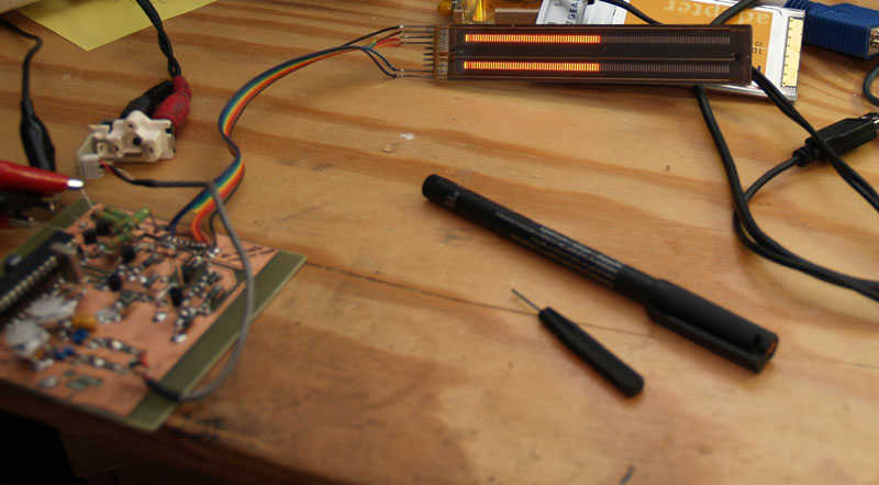
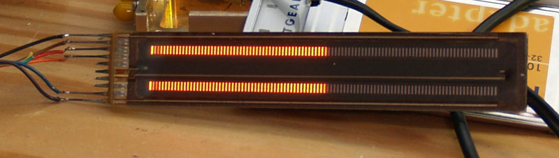
For these pictures I've modulated the controller with a stereo audio signal from my notebook's sound card. The drive level is a bit too low, but you can add any cheap operational amplifier here to increase the line level for optimum drive.
The PCB is made with the EAGLE layout program
which can be downloaded as freeware at www.cadsoft.de.
The eagle source files are available here.
The source code for the µC and a pre-compiled hex - file can be downloaded
here.
The layout for the voltage step-up-converter is available here. It's built with the common switcher IC "MC34063A".
As input driver amplifier for the af signal you can use any general purpose opamp, fet amp, ...
In conclusion this VU-meter is really an eye-catcher due to its neon-style appearance! Would look great in a tube preamp ... or in the front of a high power af - amplifier ... perhaps the next audio project ...
newest change in 06 / 2008:
The sampled input signal references to a lookup-table which converts the linear
input signal into logarithmic values for log display.
The dynamic range of my VU-Meter reaches approx. 40 dB now!
(c) Thomas Gulden, 06. 09. 2008