Building a 145 MHz high power solid state amplifier
(pictures coming soon!)
After
participating at some contests in the VHF range, "private" as DJ9KW
or with our contest crew DR2W, I decided that 100 Watts from my IC-275H aren't
enough to get the goods so I decided to build an amplifier.
So I had to choose between a tube amp and a solid-state amp project.
At the same time a friend started to build a GI-7B tube amplifier but after
some weeks we got some problems we were unable to solve at that time so I decided
to try my luck with a solid state PA (by the way the GI-7B amp works fine now,
too!).
A week before I received the recent "VHF communications" - magazine
where they explained an interesting design uning a Semelab FET "D1030UK"
with max. power dissipiation of 600 Watts an 28 Volts Ub and a drain current
of 20 Amps.
I still had a 24 - 36 Volts transformer, 20 Amps, bought at a flea market for
approx. 10 bucks on stock, so I only had to order the semiconductor and a 19"
rack case was available, too.
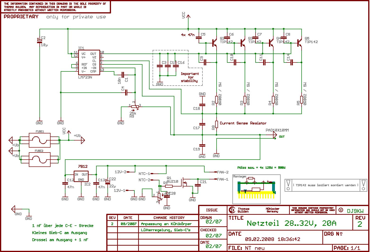
The power supply:
To
supply the FET with power, I needed a stabilized +28V voltage source capable
of delivering 20 Amps.
I decided to use a LM723 as voltage controller IC (although it's a "dinosaurus")
and some power transistors to regulate the voltage.
You can view the schematic and download the
schematic / pcb layout here. To open the layout data
you need the freeware tool "Eagle" from CadSoft.
It
is important to test the supply with a dummy load (e.g. car head lamps) to ensure
it's not oscillating at any load condition. To be sure you could also add several
100 nF as stabilizing capacitors as shown in the schematic (perhaps that's a
problem cause the LM723 is operated at its upper limit; I will try to add a
zener diode to decrease the operating voltage of this IC when I have some free
time).
Load regulation is great; no spikes when applying 100% load or disconnecting
the load.
The amplifier itself:
The
heart of the amp is as mentioned above the D1030UK FET from Semelab.
It is matched to 50 Ohms by a quarter wave transmission line with 25 Ohms (2x
50 Ohms parallel) at the in- and output.
On the input I've used 2x RG315 PTFE cable due to its roughness when accidently
touching while soldering in the PA (the earlier used RG58 didn't look really
nice after some hours of optimizing the PA ...); the output is transformed by
2x UT141 semi-rigid because it has a rather low loss, is small and allows a
"hard mounting". I could have used Aircell 7 here, too, but this is
so hard to bend and almost removed the pads on the pcb ... and remember the
soldering-iron-thing from above ;.)
After
the transmission line the FET is matched by a shunt and series capacitor and
a series inductor. The input isn't so critical, here you can play around with
some SMD C's; at the output I've used good ceramic capacitors and an air trimmer
for fine tuning and to adjust the matching if there's a real antenna connected
and not the lab dummy load to be able to tune to max. output.
The FET needs a positive gate voltage to set its idle current, this is done
by a 7812 voltage regulator followed by a divider network with capacitors to
prevent RF from entering the DC board and a 1k trimmer to adjust the quiescent
current of the FET.
Perhaps I should add an active, temperature-compensated idle current controller
because it strongly depends on the temp of the FET.
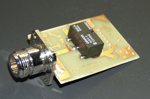
RX / TX switching:
The
RF switches consist of the types shown on my project's site.
The input switching is performed by an OMROM relais as the
FET needs about 10 Watts of drive power for 400 .. 500 Watts output power (view
schematic here).
Additionally this pcb contains a relais which pulls the RX-line to ground while
transmitting to prevent the amplifier from oscillating (isn't required but you
never know ...).
I've also added a rf rectifier with a BAT41 shottky diode whose output voltage
is proportional to the drive power, so the amplifier can be shut down when overdriven.
The pcb looks like this (only one Omron relais installed yet):
The output switching is performed by PIN Diodes as referred to at my High Power PIN RF-Switch for VHF.
"protection" circuits
SWR
Protection:
If the output VSWR is greater than 1:3 the amplifier is shut down to protect
the FET.
Current monitoring:
The current through the FET is monitored to detect oscillation (high current
in RX state) and to avoid currents > 20 A
Voltage
monitoring:
The supply voltage is monitored, so in case of a regulator malfunction (overvoltage
e.g.) the power supply will be disconnected.
(c) DJ9KW, 25. 05. 2008
Input
Power monitoring:
The drive power is monitored to shut the PA down in case somebody applies too
much power to the input to avoid damage to the FET.