Homebrew IR remote control for Olympus E-Series
After about one year of takink photos with my Olympus E-330 DSLR, there are a few things I would have "made better" in the firmware:
|
|
To solve these problems I searched the internet
and found an "Olypus Remote Control" which uses the infrared interface
of the E-330.
But unfortunately this remote had only one function: take a picture in "auto
mode".
No series function, no bulb control.
Searching a bit more I found another remote which ould have worked quite well,
but this was 99 Euro !
99 Euro for an IR remote? That's quite a lot! So I decided to give it a try and to take a microcontroller to generate the IR codes.
Step I: Getting the original IR codes and transfer protocol
For building my own remote I had to get the
IR commands and the functionality of the physical transfer layer.
Again, the internet was very great for this job: After a few hours I found a
website which contained a file I could add to the remote control program supplied
with my HP PDA (intended for controlling TV's, VCR's, satellite receivers, ...)
I was able to release the shutter via IR!
Next step was to learn these codes into my learnable universal IR remote control (one of these cheap devices where you have to hold the original remote in front of a sensor and press the knob, so it writes the received code into its memory).
Now I had the commands in my universal remote control, but this wasn't really satisfying, because I still could only shoot a picture in AUTO mode, start and stop BULB but nothing esle.
Fortunately I have an old digital sampling oscilloscope
collecting dust on top of my cupboard, so I opened the universal rc, connected
the scope to the IR LED ans saved the signal pattern.
Some "reverse engineering" later, I had the timing sequences for the
commands produced by the remote control.
THERE ARE 3 IR COMMANDS AVAILABLE:
The protocol used is the "Extended
NEC Protocol" (klick for more information).
The address used by Olympus is "0011101110000110", the data commands
are decimal "0", "1" and "2" (order as in table
above).
Step II: Building my own remote control
Now it was no problem to implement these codes
into a microcontroller.
Due to my experiences with them, I decided to use a PIC 16F876A from Microchip.
This was the time I had to decide which features I wanted to be implemented:
| |
For visualisation a 16 character 2-line alphanumeric
LC-Display with backlight, two knoba and a rotary encoder were attached to the
PIC.
The backlight of the display is PWM dimmed and switches off when there is no
user interaction for 10 seconds.
The project was written in C; the source is
available here. The source contains a pre-compiled
HEX-File which requires a 7.3728 MHz Crystal (was available in my junk box)
for IR timing generation and time counting functions (exposure and interval
time).
The PCB was created using the freely-available CAD-tool "EAGLE". The
schematic and pcb layout can be downloaded here.
The finished PCB was glued into a plastic box
with a milled hole for the LCD.
Power source is a 3.6 volts Li-Ion cell from an old notebook (nearly no self-discharge).
...and this is what it looks like:
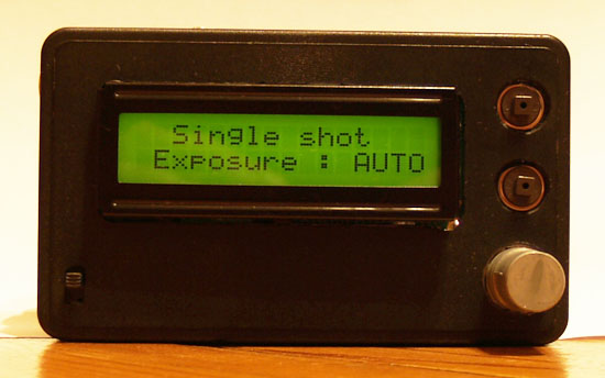
Top Button: take picture / start bulb (depending
on menu)
Second Button: Change item which should be adjusted / stop bulb (depending on
menu)
Encoder-Pushbutton: Switch to next menu (see implemented features listed in
table above)
Encoder-turn: Increase / decrease item
Switch on lower left: Power on / off
For greater coverage I've put an Transistor as emitter follower at the output
of the PIC (where the IR-LED is installed in the schematic) to drive 6 LEDs
installed around the housing.
If I find the time, I will re-write the code
,because it is a bit hard to maintain due to the loops calling each other.
There is also a bug when you use the "exposure series" feature and
choose an exp. time smaller 2 seconds.
The timing (1 sec delay) is implemented by a counter increasing every call of
the main loop; it would be more accurate and flexible if this counter was controlled
by an interrupt which derives its clock from the crystal.
(c) Thomas Gulden, 06. 09. 2008