HP 8562A span accuracy: the peak that wouldn't sit still
After bringing this 8562A back to life with a power supply repair, it rewarded me with one of the more interesting faults I've chased in a while: a frequency display error that existed only in a specific window of span settings - and turned out to be a 40 year old VCO quietly drifting out from under HP's own auto-calibration.
The symptom
Measuring a 10 GHz signal, the peak sat perfectly centered at wide spans and at very narrow spans - but at 50, 100 and 200 kHz span it was displaced visibly to the left of center, with the marker readout following the displaced trace. The displacement was a roughly constant fraction of span (~3-4 %), not a constant number of Hz. That ratio is the first clue: a fixed Hz offset means a tuning error; a fixed fraction of span means a sweep gain error.
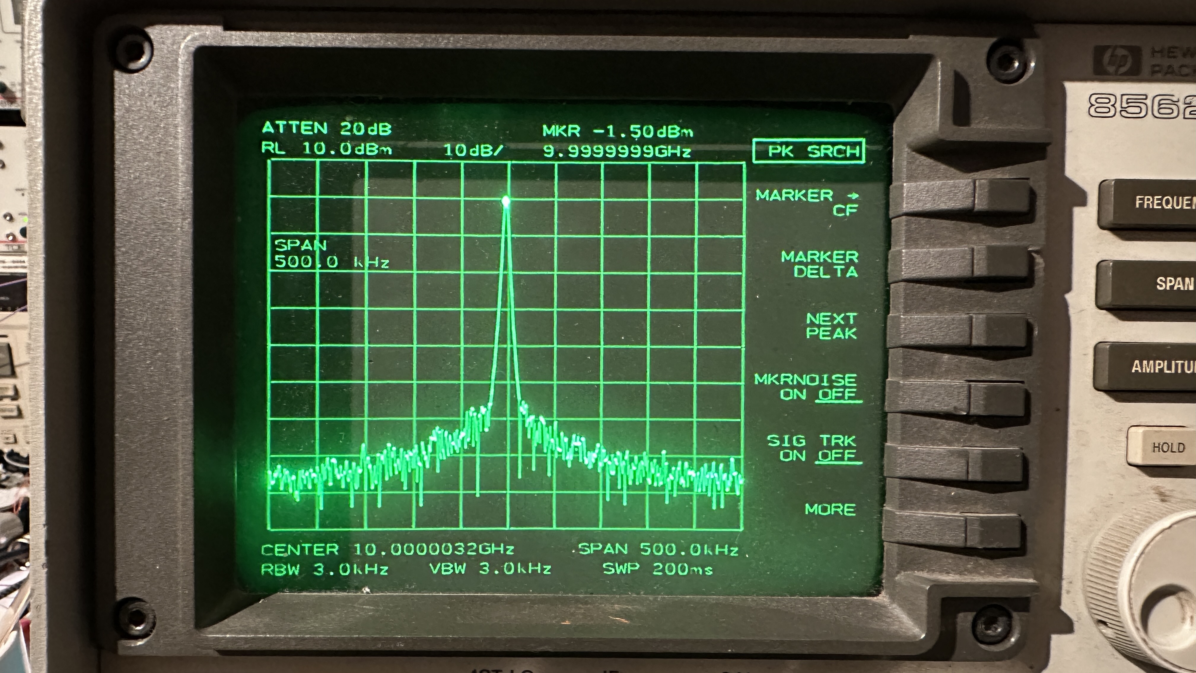
Reference shot: 10 GHz at 500 kHz span - peak correctly centered
Getting ground truth
At 10 GHz I had no absolute reference on the bench, so I switched to the internal 300 MHz calibrator - which is derived from the analyzer's own timebase and therefore exact by definition in the instrument's frame. Stepping through the spans and recording (marker - 300 MHz):
| Span |
Marker reads |
Error |
Error / span |
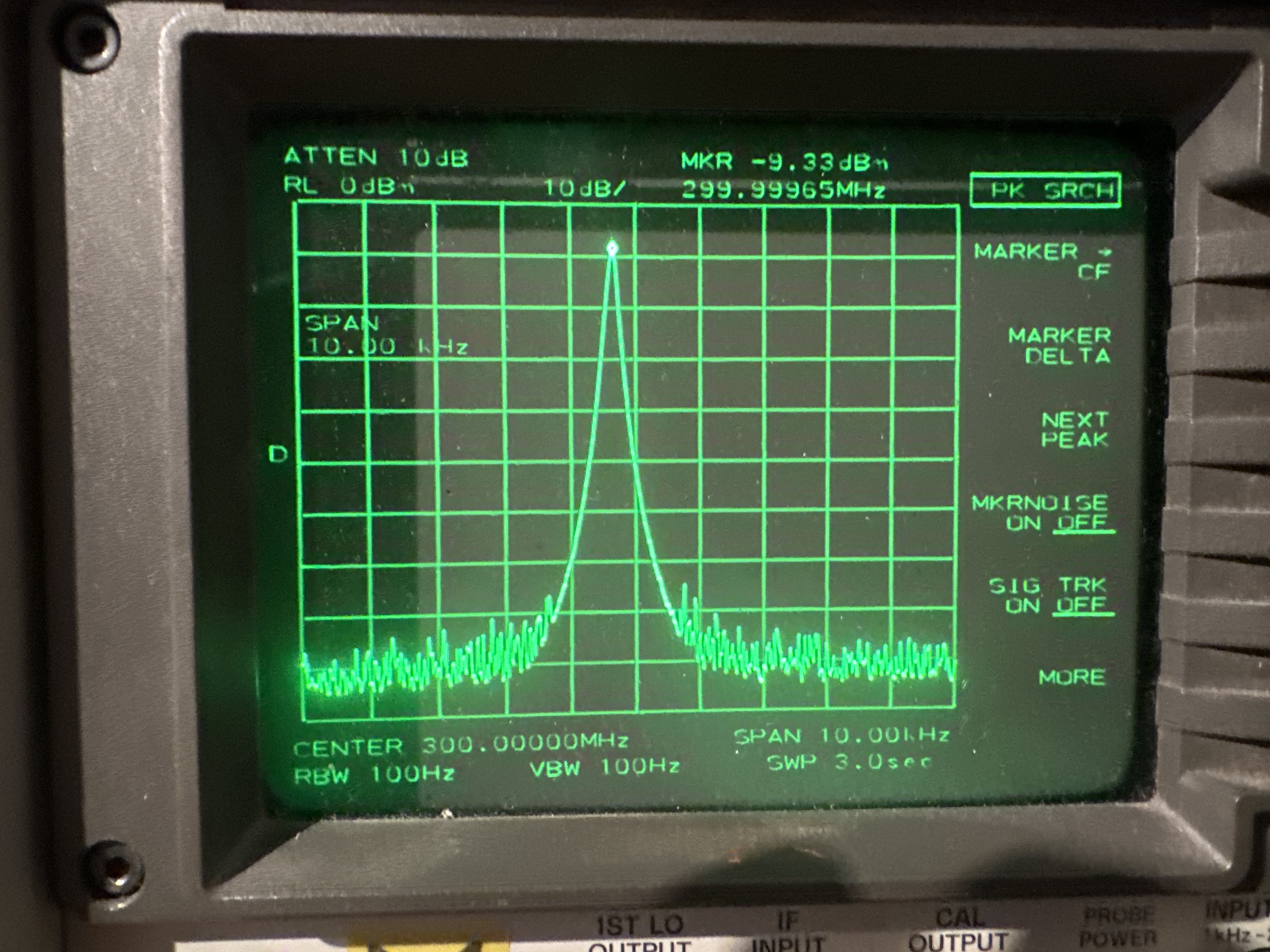
| 10 kHz | 299.99965 MHz | -0.35 kHz | -3.5 % |
| 20 kHz | 299.99937 MHz | -0.63 kHz | -3.2 % |
| 50 kHz | 299.99833 MHz | -1.67 kHz | -3.3 % |
| 100 kHz | 299.9960 MHz | -4.0 kHz | -4.0 % |
| 200 kHz | 299.9993 MHz | -0.7 kHz | -0.35 % |
| 500 kHz | 299.9958 MHz | -4.2 kHz | -0.84 % |
| 1 MHz | 299.992 MHz | -8 kHz | -0.8 % |
The title picture above shows the fault against this ground truth: the 300 MHz calibrator at 10 kHz span, with the peak sitting ~0.35 divisions left of center.
Two surprises. First, the narrow spans were not actually clean - at 10 GHz they had only looked correct because I had centered via MKR->CF on an equally shifted trace, a perfectly self-referential error :-) Second, the error had a razor-sharp boundary between 100 and 200 kHz span.
A useful trick along the way: FREQ COUNT read exactly 300.00000 MHz throughout. The counter halts the sweep and measures with the loop closed, bypassing the sweep ramp entirely - so a perfect count with a shifted trace cleanly separates "synthesis chain healthy" from "sweep display broken". It also makes (marker - count) a precise span-error meter that needs no external reference.
Thinking in LO spans
The 10 GHz measurements (2nd-harmonic mixing, N = 2) and the 300 MHz measurements (N = 1) disagreed about which RF spans were bad - until converted to first-LO span (RF span / N). Then both datasets agreed exactly: LO spans up to 100 kHz were off by ~3-4 % of span, LO spans of 200 kHz - 1 MHz were fine.
The 856xA/B service manual ("Frequency Span Accuracy Problems", p. 10-15 ff.) explains why that boundary exists. Table 10-6 maps LO span to sweep mechanism:
| First LO span |
Swept element |
| > 20 MHz | YTO main coil |
| 1.01 - 20 MHz | YTO FM coil |
| 101 kHz - 1 MHz | Main Roller Oscillator |
| up to 100 kHz | Offset Roller Oscillator |
My fault boundary was the architecture boundary. In spans of 100 kHz and below the Offset Oscillator is swept open-loop over 100x the LO span (10 MHz of roll for a 100 kHz span) while the Main Roller stays locked to offset/100 and the YTO tracks the Main Roller. Step 8 of the manual's troubleshooting procedure is written for precisely this case:
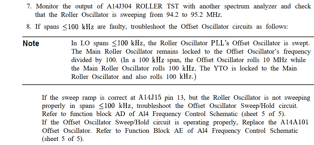
Service manual: Offset Oscillator troubleshooting, step 8
Measuring at the source
The manual provides A14J304 ROLLER TST for observing the roller directly. With a second analyzer on that port:
| Setting |
Expected roll |
Measured |
| 1 MHz span (Main) | 94.2 - 95.2 MHz | 94.2 - 95.2 MHz, fine |
| 100 kHz span (Offset) | 94.65 - 94.75 MHz | 94.65 - 94.76 MHz - ~110 kHz, ~+10 % |
Note the detail: the start frequency was exact (that point is synthesized before the loop opens); only the top end overran. A pure gain error, zero offset - matching the constant-fraction displacement on screen. My second 8562A, pressed into service as a golden reference, showed a textbook 100 kHz roll at the same settings.
Into the schematic
Function blocks AC/AD/AE/AF on A14 sheet 5 of 5 tell the story of a span of 100 kHz or below: the PLL error voltage is frozen by U112 (an LF198 sample-and-hold, C363 holding), the OFFSPAN ramp is switched in through U116D (DG212) and summed via the R389 / R335 / R340 ladder onto the held voltage, buffered by U111B, and applied to the A101 oscillator's coarse tune input.
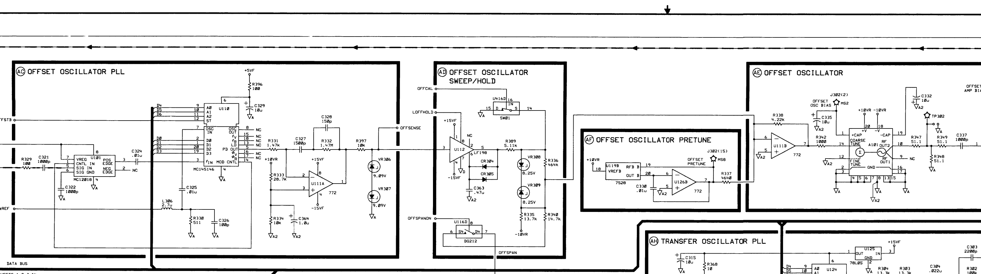
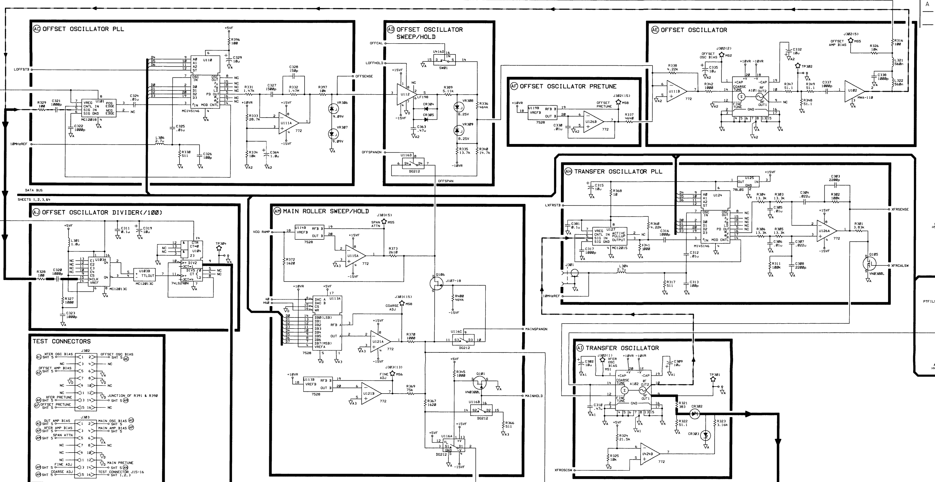
A14 sheet 5: the offset oscillator sweep/hold blocks and the wider view
And this is how it looks in the real world - the A14 board on the bench (the tweezers pointing at the R340 spot next to U112) and the manual's parts location drawing with R340 highlighted. One caveat worth stating clearly: schematic and parts location in the manual are drawn for the other A14 HP part number - my real PCB (08562-65074) has subtle differences to these drawings, which will come back to bite in Act III...
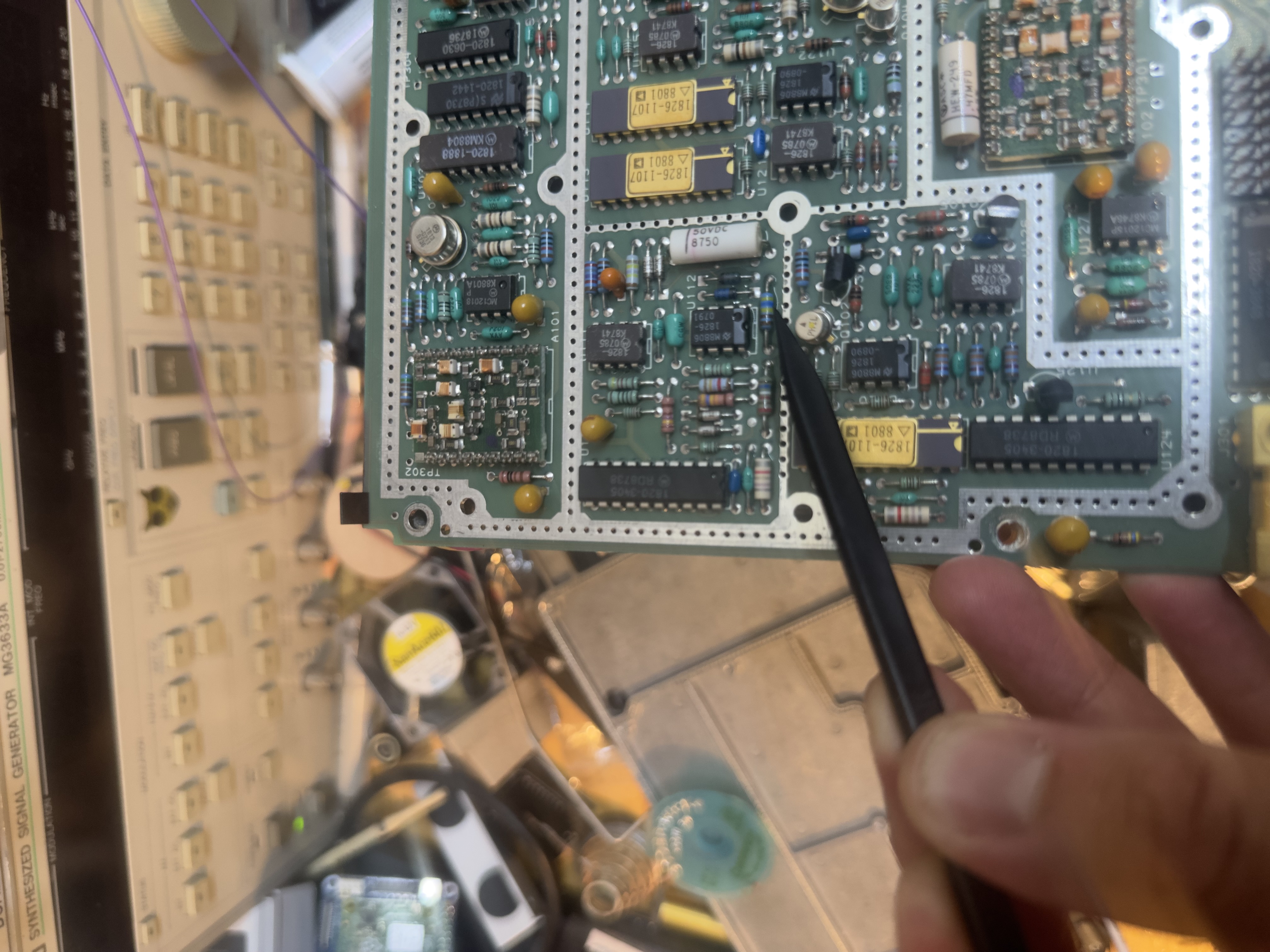
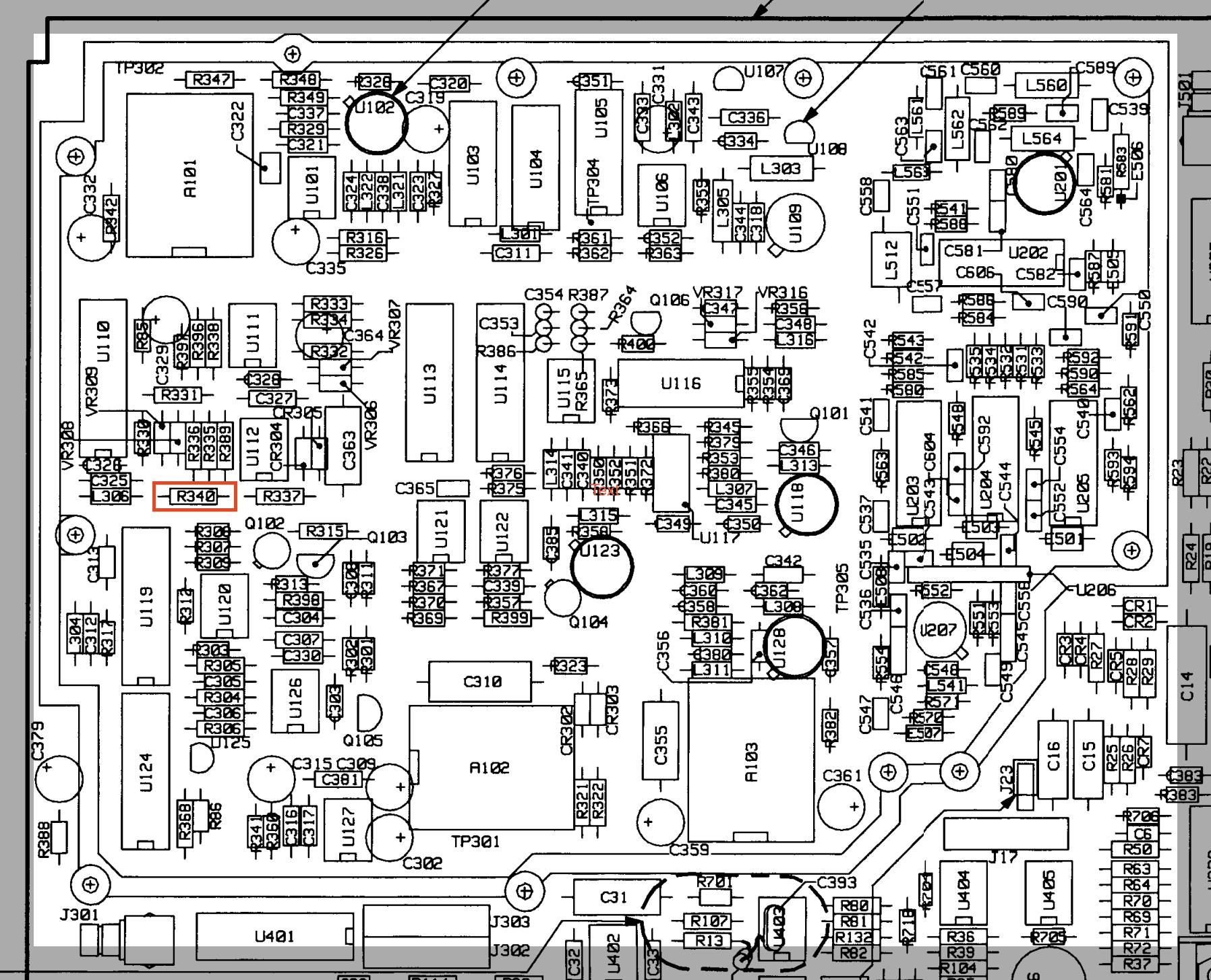
The real A14 board and the parts location drawing with R340 marked in red
The measurement data had already eliminated most suspects. Hold-cap droop would scale with sweep time (it didn't - 2 s and 300 ms sweeps showed the same fractional error). Degraded switch resistance sits in series and would make the roll too narrow, not too wide. The span attenuator upstream was exonerated by the perfectly healthy 200 kHz - 1 MHz spans it also serves. That left the ladder resistors and the oscillator's own tuning slope - and every resistor in the ladder measured bang on nominal.
The fix: two kilohms of humility for a drifted VCO
By elimination, A101's tuning sensitivity (Hz/V) has increased ~10-12 % over four decades - the varactor operating point sliding onto a steeper part of its curve. The PLL is completely blind to slope: it parks the tune voltage wherever the frequency is right, so lock, counts and start frequencies stay perfect while every open-loop roll comes out too wide.
The compensation point is R340, the resistor that carries the OFFSPAN ramp exclusively (everything else in the network also touches the PLL, the hold path, or the healthy Main Roller spans). Scaling the roll by x0.89 meant raising the injection branch impedance accordingly: R340: 14.7 kOhm -> 16.83 kOhm.
Result: every span from 10 kHz to full span now places the calibrator dead center, verified with the marker-vs-FREQ COUNT method across the range and spot-checked at 10 GHz. The original resistor is taped to the A14 board with a note, for future archaeologists. (Keep reading - that resistor has a second act.)
Prior art: the same disease, terminal stage
While hunting I stumbled over a closely related case on EE Archeology: an 8562A whose Main Roller VCO (A103) - the same circuit family as A101 - had drifted so far in its V/f characteristic (traced to contamination/degradation of the module substrate) that the mixer product left the loop filter's passband and the loop lost lock entirely, with the phase detector falsely reporting lock. That one was ultimately fixed by module replacement:
HP 8562A 1kHz-22GHz Spectrum Analyzer Repair, EE Archeology (Roller Oscillator repair in section IV)
The most valuable exhibit from that repair is this f/U comparison of a good versus a drifted roller VCO module, measured over the coarse tune range - "borrowed" here (with credit, from the page linked above) because it may come in handy if anyone ever needs a healthy tuning curve for comparison:
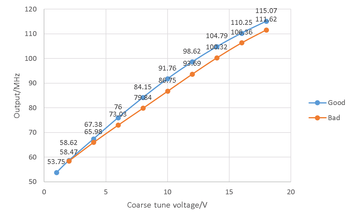
Good vs. drifted roller VCO tuning curve (image (c) lhf / EE Archeology, 7400.me)
My A101 appears to be the same failure mode caught early: drifted enough to spoil the open-loop span calibration, not yet enough to unlock. Worth knowing for every 8561A/8562A/B owner - these little roller VCOs age.
Act II: ERR 315, and the trim that wouldn't sit still
Shortly after declaring victory, the analyzer began reporting ERR 315 FREQ ACC - while measuring perfectly. Per the service manual, ERR 315 fires when the Roller Span Attenuator DAC (U114B) value, recalculated on every span or start-frequency change, falls outside its 10-245 window. The theory of operation explains why the firmware even has an opinion: at every power-on, the LO ADJUST sequence steps the pretune DACs, finds lock points every 2 MHz, measures the rollers' tuning sensitivities, and trims U114B to improve span accuracy. The instrument had been watching A101 drift for years and silently compensating - until the correction budget ran against its rail.
Then came the more telling observation: the R340 trim was a moving target. Dialed to spot-on with a trimmer, it needed dialing up again after a power cycle and the accompanying LO/roller readjust. The firmware partially sees the injection network during its power-on measurement, recalculates its own U114B share against the analog trim, and the two corrections settle into a new joint equilibrium - a tug-of-war. Trimming on the wrong side of an auto-calibration gets you exactly this: a value that walks after every cold start, and a span DAC pinned at its limit filing complaints.
The R338 experiment (or: the objection that half-won)
Staring at the schematic again settled where the trim actually belongs. The offset oscillator's pretune (via R337) and the combined PLL/sweep signal (via R336/R340) sum at the same node - U111B's inverting input - and R338 (4.22 kOhm) is the feedback resistor of that stage. It therefore scales pretune, PLL correction and sweep by the same factor: change R338 and the entire coarse-tune drive behaves as if A101 still had its nominal Hz/V. Crucially, that composite is what the firmware's sensitivity measurement actually probes, so a correction here should be visible to LO ADJUST - letting the span DAC return to mid-range and ERR 315 retire honestly, instead of being worked around. As a bonus the loop dynamics improve rather than degrade: A101's steep slope has been running the offset PLL ~12 % above its design loop gain for years.
The plan: R340 back to its original 14.7 kOhm; R338 replaced by a 10 kOhm trimmer preset to 4.22 kOhm (wiper tied to one end terminal, so a scratchy wiper fails to maximum resistance instead of an open feedback loop), then dialed down toward the predicted ~3.8 kOhm. Because the firmware re-measures at every boot, the protocol is power-cycle-in-the-loop: dial, cold start, marker-vs-FREQ COUNT at 50 and 100 kHz span, repeat.
Result: the objection was right about the circuit and wrong about the firmware. R338 behaved exactly like R340 had - dial to spot-on, realign the LO and rollers, find the target has moved, dial again, converge with the trace exact... and ERR 315 back on screen. Both trim locations end in the same equilibrium: perfect spans, unhappy bookkeeping. Whatever the span-DAC computation is anchored to, neither resistor reaches it; the only correction the firmware would accept as "nominal" is A101's actual slope. The honest conclusion: the error message has been telling the truth the whole time - this VCO is drifted - and every external compensation, however well placed, leaves it standing.
Act III: probing the span attenuator (or: how to read a 1987 mind)
Chasing ERR 315 to its named hardware turned into a small reverse-engineering exercise, with a few lessons about probing current-mode circuitry the hard way.
First finding: the offset pretune DAC (U119B) sits mid-scale - about 6 V of a 10 V reference - so the pretune system has healthy headroom despite the drifted curve. The error is not about lock effort.
Second finding, after falling into the classic multiplying-DAC probing trap (the OUT pins read ~0 V at every code - they carry current into a virtual ground, not voltage): U115A's output shows a sawtooth only at spans above 100 kHz and sits at zero below. The regime split is real and measurable - U114B/U115A scale the ramp for the Main Roller spans only. Yet the OFFSPAN net demonstrably carries a ramp in the offset regime, so the ramp bus must have a second driver - per schematic a FET switch (Q106) fed from the sweep-generator side, bypassing U114B entirely.
Which reframed U114B itself. It's called the span attenuator because that's literally what it is: the VCO ramp enters the 7528's reference input at fixed amplitude, the 8-bit code sets the R-2R ladder's transmission, and the output delivers ramp x D/256 - a programmable analog multiplier in one part. The firmware's 10-245 window is simply the ladder's usable linear region. ERR 315, translated: "my analog gain knob has left its linear range" - and with the offset ramp riding past U114B, most likely a low-side violation that affects the actual sweep not at all.
The chase through this corner ended with a discovery that deserves its own warning label: the board on the bench (revision 08562-65074) differs substantially from the schematic in exactly this area - the Q106/J107-18 arrangement isn't fitted on this revision at all. Probing a circuit against a non-matching schematic revision is a trap with no bottom, so the reverse engineering stopped there, honorably. The definitive proof would be a logic-analyzer capture of the bytes written to U114B across a span tour, stock versus trimmed - each byte is the gain, no interpretation needed. That capture is left as a possible sequel; the analyzer had already earned its way back onto the bench.
Final state
In the end, pragmatism won. The R338 modification was reverted - touching the PLL's feedback for no firmware benefit is a poor trade - and the surgically-confined R340 correction went back in. After the firmware's power-on tug-of-war finished moving the target, the value settled at R340 = 18.5 kOhm (up from the first landing at 16.83 kOhm), soldered in as fixed resistors with the trimmer retired, and recorded in the lab reference book and on the note taped to A14 beside the original part. The instrument went back together wearing its ERR 315 like a service ribbon - with a remark added to the top cover telling future-me to ignore it, so nobody re-runs this investigation in 2035 :-)
And the closing measurement is the one that matters: side by side with the second 8562A - the one with no error and no history - performance is identical. Spans exact from 10 kHz up, counts dead-on, the error annunciator the only distinguishable difference. The standing ritual: thirty seconds with the internal calibrator (marker minus FREQ COUNT at 100 kHz span) and a scroll through RECALL ERRORS, watching for anything that isn't 315. If the span error ever grows past ~1 %, that's the pre-agreed trigger for A101's cleaning - or its transplant from a donor, the one repair that would finally make the instrument and its firmware agree.
Its reward for surviving all this: honorable reserve duty. This unit now lives under the desk as the fully working spare - instantly deployable if the daily-driver 8562A ever falters, and a complete, characterized parts source in the worst case. Given what these two have been through together, it seems only fair they look after each other.
As always, the analog companion to this story lives in the lab reference book - the annotated sweep/hold schematic with the trim marked in red, the A14 component layout with A101 and R340 highlighted, the R338 detour recorded as "Versuch 2" with its verdict, and the alternatives noted for the day the drift resumes:
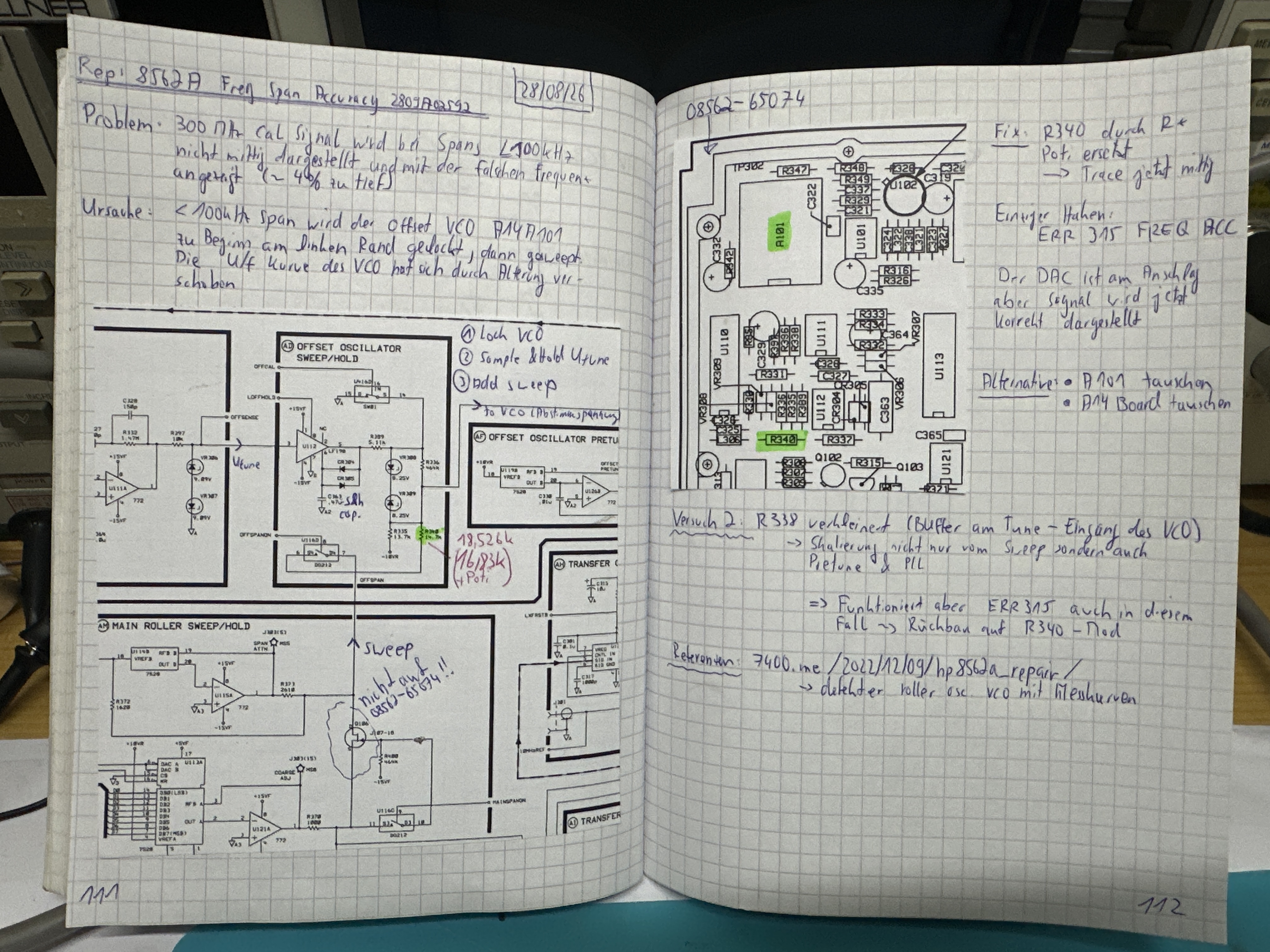
Lab reference book, pages 111-112
Sidebar: why a 1987 instrument trusts its VCO slope
It seems odd that the design depends on the slope of a VCO when the firmware already measures lock points by injecting pretune values. But that is a snapshot of 1986 trade-offs. The measurement exists - LO ADJUST is exactly "inject pretune voltages and see where it locks" - what is limited is the correction authority attached to it: an 8-bit DAC with guard bands, budgeted for the +/-5 % span spec against expected production tolerances, not four decades of varactor drift. There is a modeling gap, too: a lock-point measurement yields the local small-signal slope, while a 100 kHz span rolls the offset oscillator through 10 MHz of a curved characteristic - the sweep integrates the curve, the calibration samples points on it. And the open-loop roll itself is a deliberate purity choice: a held oscillator on a clean ramp has no loop steering it mid-measurement, no phase-detector artifacts inside a 100 Hz RBW. Continuously-locked swept synthesis at useful rates had to wait for the fractional-N of the 8560E generation - which deleted the rollers entirely.
Lessons for the toolbox
A displacement that is a constant fraction of span is a sweep-gain error; a constant number of Hz is a tuning error - the distinction cuts the suspect list in half before the covers come off. Ground truth matters: MKR->CF happily hides a display error by centering on it, while the internal calibrator plus FREQ COUNT gives a reference-free span-error meter. Converting symptoms to first-LO span (divide by the harmonic number) is what made two contradictory datasets agree and land exactly on a hardware regime boundary. When an instrument self-calibrates at boot, any analog trim must sit on the measured side of that calibration - otherwise you get a moving target and a correction DAC pinned at its rail - and every trim iteration must include a power cycle. Current-mode circuitry hides its signals by design - virtual grounds null every summing node, multiplying-DAC outputs read zero volts at any code - so the information lives at op-amp outputs, across summing resistors, and on the test connectors HP thoughtfully exported; probe those, not the junctions. A second unit of the same model remains the best piece of test equipment money can buy. And an error message can be simultaneously true and harmless: ERR 315 correctly reports that this instrument no longer matches its 1987 assumptions, while the measurements prove it no longer matters.
References: HP 856xA/B Service Manual - "Frequency Span Accuracy Problems" (p. 10-15), Table 10-6, ERR 314/315 descriptions (Ch. 6), Roller Span Attenuator DAC theory (Ch. 10); schematic and manual excerpts (c) Hewlett-Packard / Keysight, reproduced here for repair documentation purposes.
(c) DJ9KW