Reverse Engineering the TCL Inverter Minisplit IDU-ODU S-Line Protocol
This one's a bit different from the usual HP repair stories. The goal: reverse engineer the serial communication between the indoor unit (IDU) and outdoor unit (ODU) of a cheap TCL inverter minisplit air conditioner. Why? Because I want to replace the IDU with a custom ESP32 controller and repurpose the ODU as a hydronic heat pump for floor heating, with PV-optimized constant-power operation via Tibber dynamic pricing. Sounds crazy? Maybe. But the compressor has a 6:1 turndown ratio and the ODU board turns out to be way more capable than expected.
The target is a TAC-12CHSD/XA41I-QC, a budget 12K BTU R32 inverter minisplit, picked up as a donor unit for 180 EUR. At that price, I just couldn't say 'no' when spotting it on ebay marketplace (now Kleinanzeigen). Only ran for one year and just 20 minutes away! This unit was meant to be picked up by me! Not that i didn't collect enough junk by now, this one unit can't make it that worse :-)
I am planning on setting up a little test bench on my paddio but the weather is fighting my plans as it is cold and windy. While thinking of how to proceed, I think about my living room unit which is currently heating the house. It's a "Hantech" branded one but I know that the TCL and Hantech remote are interchangeable. So maybe the protocol running over the single wire ("S-Line") between indoor unit (IDU) and outdoor unit (ODU) are the same ?!? As time proves: Yes, they are! and even better, my 6 years older TCL unit in the bedroom uses exactly the same protcol, too! It seems, most of these cheap minisplits are quite similar!
The S-Line: A Current Loop at 625 Baud
Three wires connect the IDU and ODU: AC Live, Neutral, and the communication "S" wire. The S-line uses a current loop, powered by a 24V DC supply from the IDU. Both units have identical optocoupler circuits (PC817) that modulate the loop current. The idle state sits at about 10V on the S wire. When the IDU transmits, it removes current from the loop and the voltage rises to ~15V. When the ODU transmits, voltage drops to ~5V. Both sides effectively "pull" in opposite directions by switching their optocouplers off. It's a pull-pull topology, quite elegant for a budget unit.
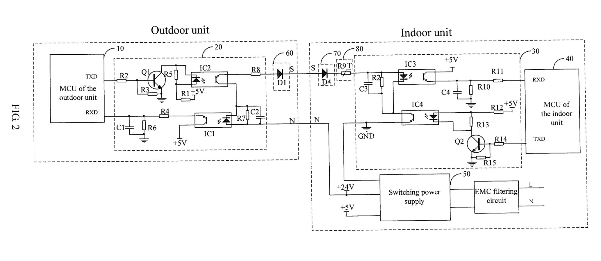
Midea patent EP3644519A1 FIG. 2 showing the current loop circuit, confirmed identical on the TCL board
Only difference is the polarity of the optos: on my units, the anode leg of the opto has to point towards the IDU while the cathode of the opto has to go towards the ODU. So exactly vice versa as in the Midea patent. But everything else seems to be identical.
Serial parameters: 625 baud, 8 data bits, even parity, 1 stop bit. The RC filter (5.1k + cap parallel to each opto LED) rejects high frequency noise while passing the slower data transitions. I confirmed the baud rate and bit timing on the scope with cursor measurements: 1.6ms per bit cell = 625 Hz.

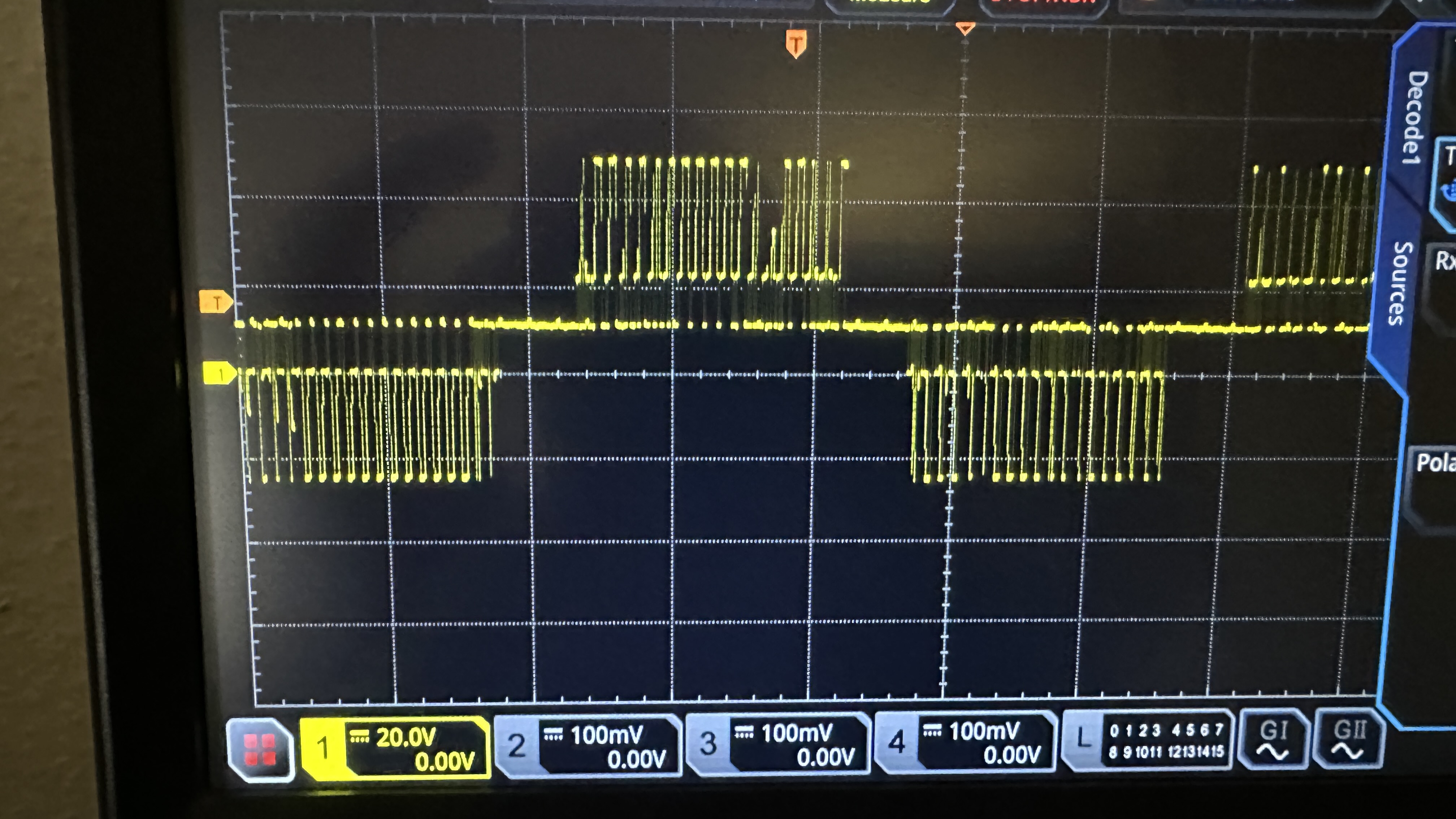
Clean UART waveform showing individual bit cells at 1.6ms
Protocol Framing: 19 Bytes, 6 Packet Types
All packets are 19 bytes: sync (0xAA), address (0x01), type, length (0x0D = 13 bytes payload), 13 payload bytes, end marker (0x55), and a checksum. The checksum is delightfully simple: the sum of all 19 bytes equals 0xA9 mod 256. The constant 0xA9 likely derives from 0xAA + 0x55 = 0xFF, and 0xFF + 0xAA = 0x1A9.
Six packet types cycle continuously at ~3 second intervals, even in standby:
0x01 - ODU status: compressor frequency, 4-way valve, mode, EEV position
0x02 - ODU Sensor data: discharge, coil, and ambient NTC readings (raw 8-bit ADC values)
0x14 - Heartbeat poll ???
0x81 - IDU Response: mode status, setpoint (CRT), fan speed, turbo flag
0x82 - IDU Response (variant of 0x81)
0x84 - IDU Heartbeat response with fan mode ???
The response type formula is neat: response = (request & 0x0F) | 0x80. So 0x01 maps to 0x81, 0x02 to 0x82, and 0x14 to 0x84.
The ODU Board: More Than Expected
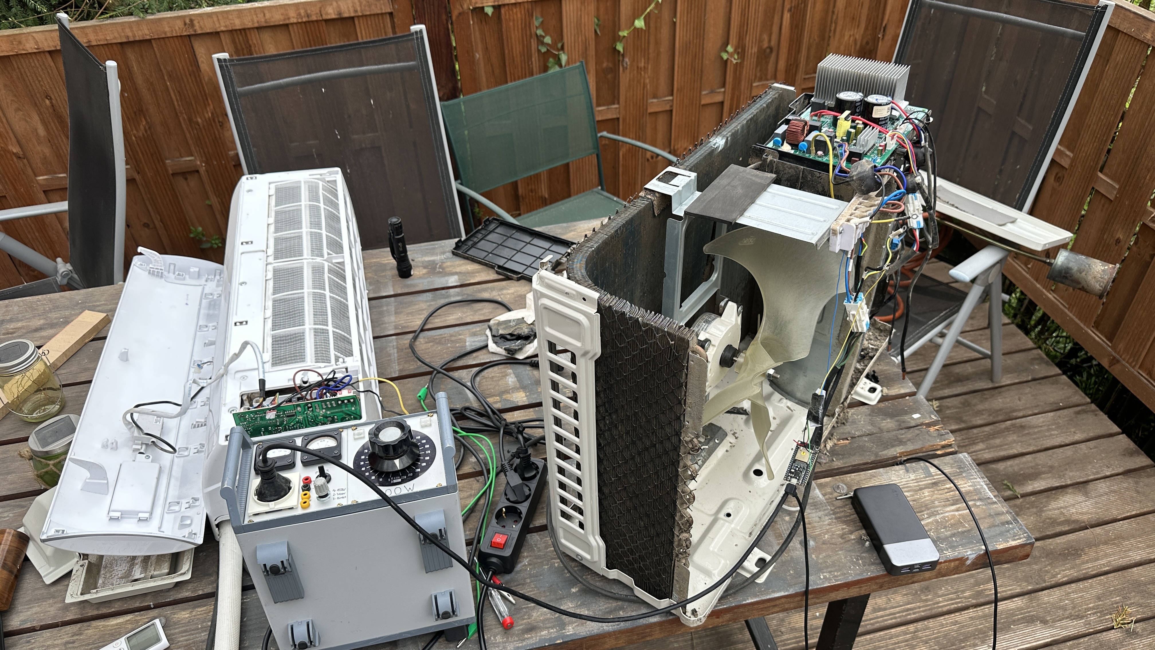
Opening up the donor unit for PCB inspection was full of surprises. The board (A010313 V1.0) runs a Texas Instruments TMS320 DSP, not a cheap 8-bit micro. This thing is capable of proper motor control, PFC, and has multiple UART peripherals. However, the low-voltage supply is NOT isolated from mains but tied to the negative pin of the mains rectifier so do your probing on your own risk and don't blow up your scope!
All test points are at mains potential. The S-line optocouplers are the only isolation barrier. Lesson learned: always use an isolation transformer when probing this board.
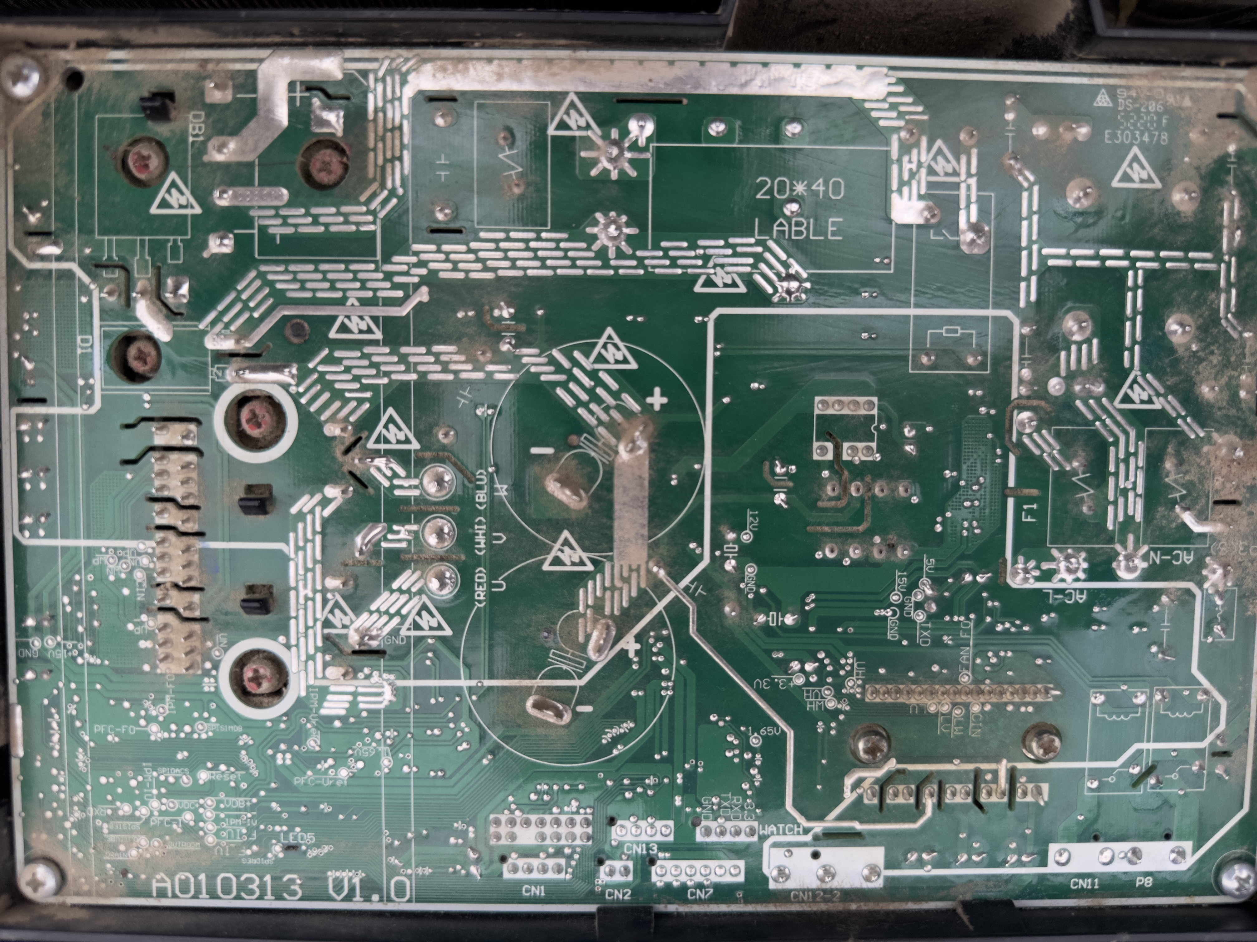
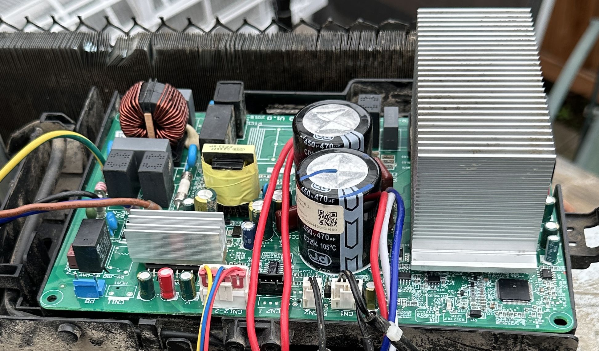
ODU board A010313 V1.0 solder and component side
EEV Driver: Not Populated, But Firmware Is Ready
Here's where it gets interesting.
In my naive mind, I always assumed all those inverter mini splits are equipped with an electronic expansion valve instead of a boring capillary tube. I was quite disappointed to realize they didn't just use a capillary in this system but also saved some pennies and left the driver chip and connector unpopulated! What a bummer! Looking closer at my other two units, the more recent one, the Hantech R32 inverter unit, also has no EEV, but the 6 years older R410A bedroom unit has one! Perfect for later comparisons!
Well, a SO16-IC is unpopulated but you can clearly see, which pins are connected to the EEV connector and which pins go to the TMS320. Looks suspiciously like a ULN2003! And a look in the datasheet proves my assumption. Damn, I'm out of stock and have to order some but the AliExpress Sanhua DPF11.3C EEV takes a couple weeks to get here nonetheless...
In the meantime I start probing a bit on the pins of the ULN2003 that go to the TMS and voil�, during startup and shutdown there is some wiggling going on! My assumption is that the firmware dowsn't bother whether an EEV is installed or not. There might be an inner control loop which tries to adjust it and once conditions run out of its scope, another control loop (compressor speed, fan speed, ...) steps in, just a bit coarser than with an EEV. I guess the EEV would result in a 10..15% better overall efficiency but that's just a rule of thumb.
When probing the EEV pins at startup, I see a 196-step homing routine at 4 Hz (49 seconds), followed by positioning to an operating point. The firmware is universal and doesn't know (or care) whether an actual EEV is connected.
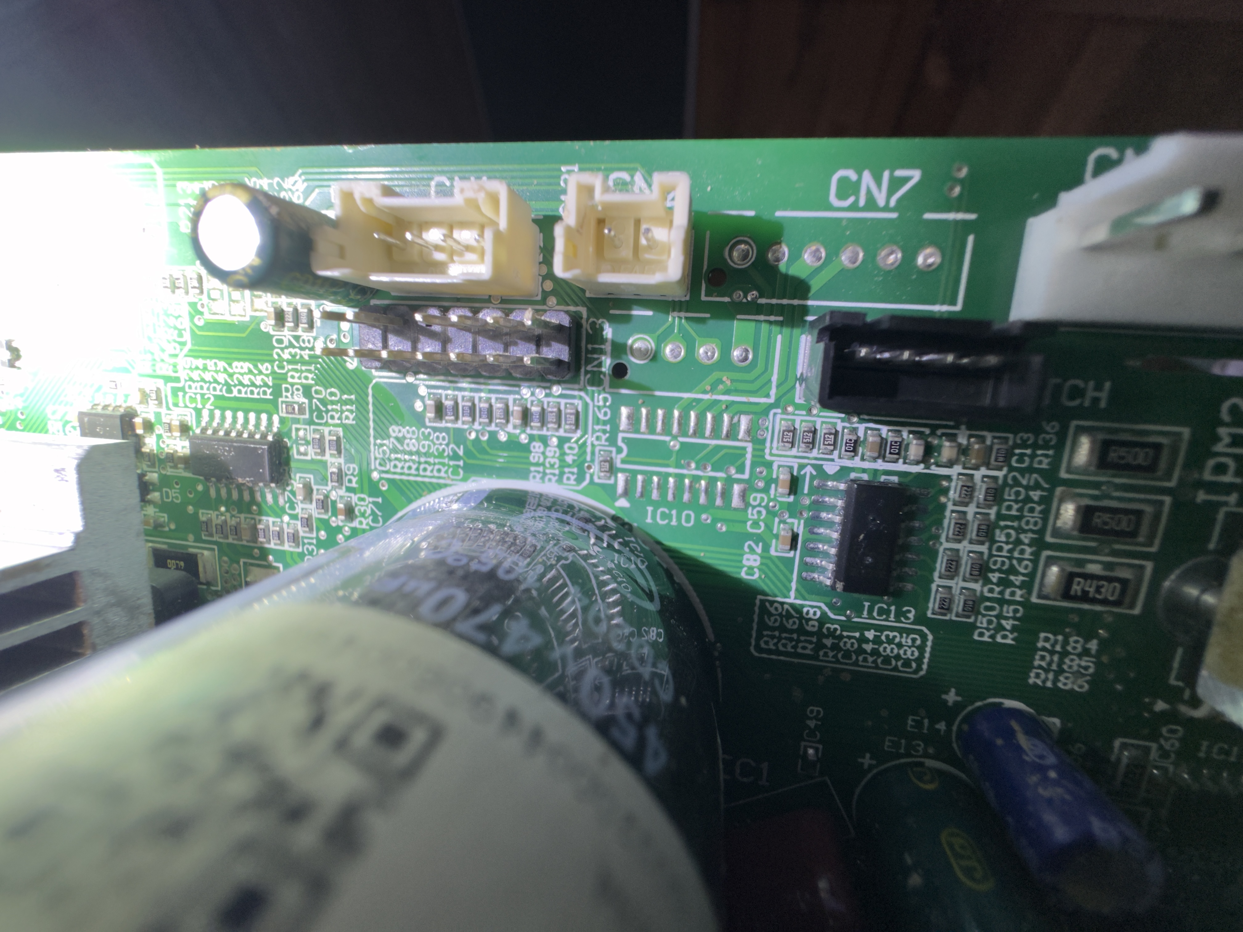
CN7 EEV connector and IC10 ULN2003D footprint, both unpopulated on the budget model
Sniffing the Bus: ESP32 WiFi Bridge
Capturing data packets with an scope sitting underneath the living room IDU works for a first test but is rather inconvenient. So let's get an ESP32, flash it with a Serial-to-TCP firmware and get started in python to write a parser for the packets. In my firmware I cn enter arbitrary baud rates, switch between no/even/odd parity and normal or inverted serial mode. I think this will come in handy in other projects, too!
For continuous bus monitoring I built a simple passive sniffer: a single PC817 optocoupler in series with the S-line (with the matching 5.1k + 100pF cap parallel filter), feeding an ESP32 UART RX at 625 baud 8E1. The ESP32 forwards raw bytes over TCP/WiFi. Full galvanic isolation via the optocoupler, no risk of mains contact.
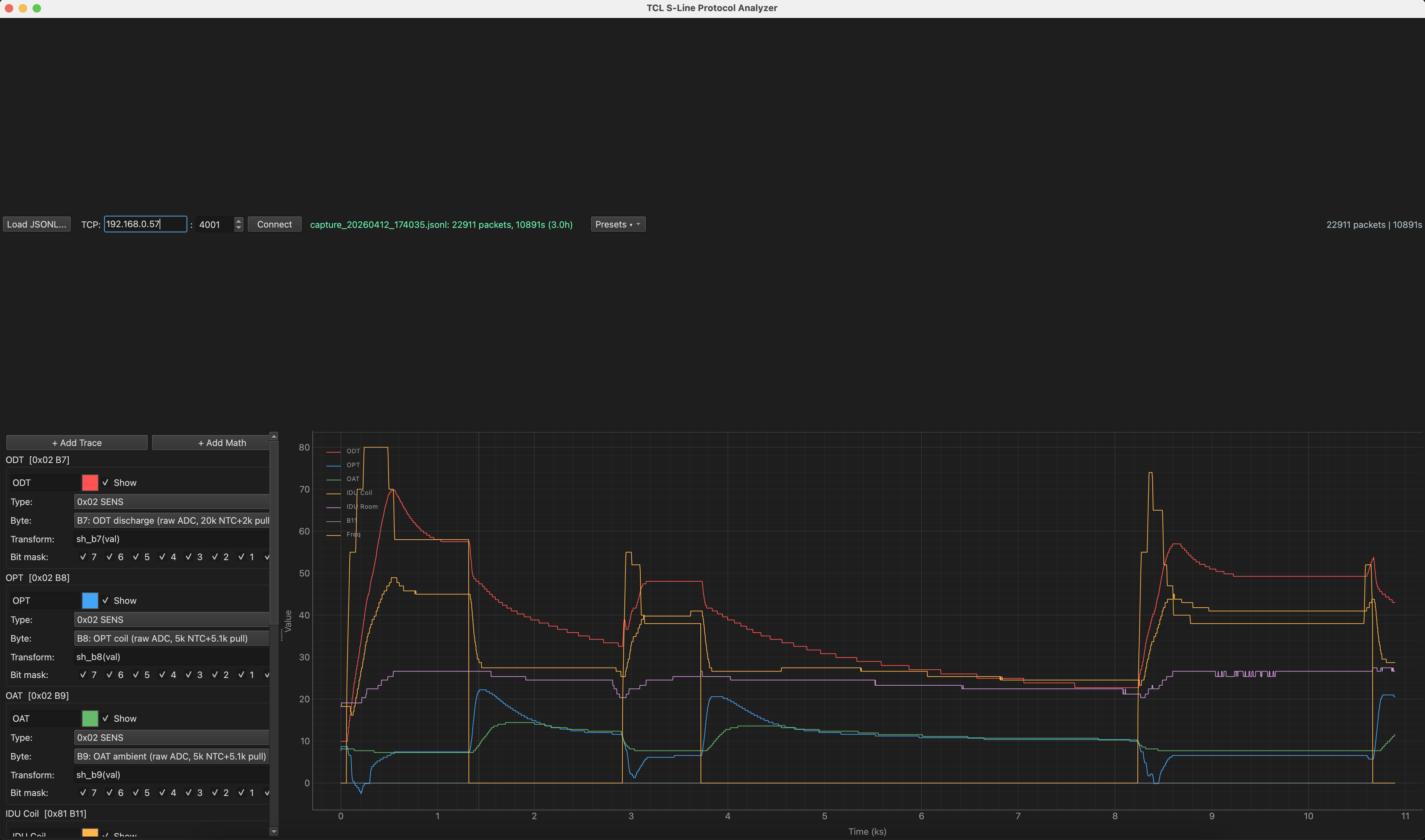
On the PC side, I wrote two Python/PyQt6 tools. The first is a real-time bus monitor with a decoded dashboard showing all temperatures, compressor frequency, mode, EEV state, and fan settings. The second is a protocol analyzer for post-processing captured data: plot any byte from any packet type with custom transforms, bit masking, and math traces. Both connect live to the ESP32 via TCP or replay captured JSONL files. By the way, the files use the TomTerm export format and are interchangeable with it. Dark theme, because lab work at midnight demands it.
If you want to play along:
- requirements.txt
- tcl_analyzer.py : capture, record, show all current system parameters live
- tcl_bus_monitor.py : post analyze a capture, zoom in graphs, math functions on graphs. Also supports live mode.
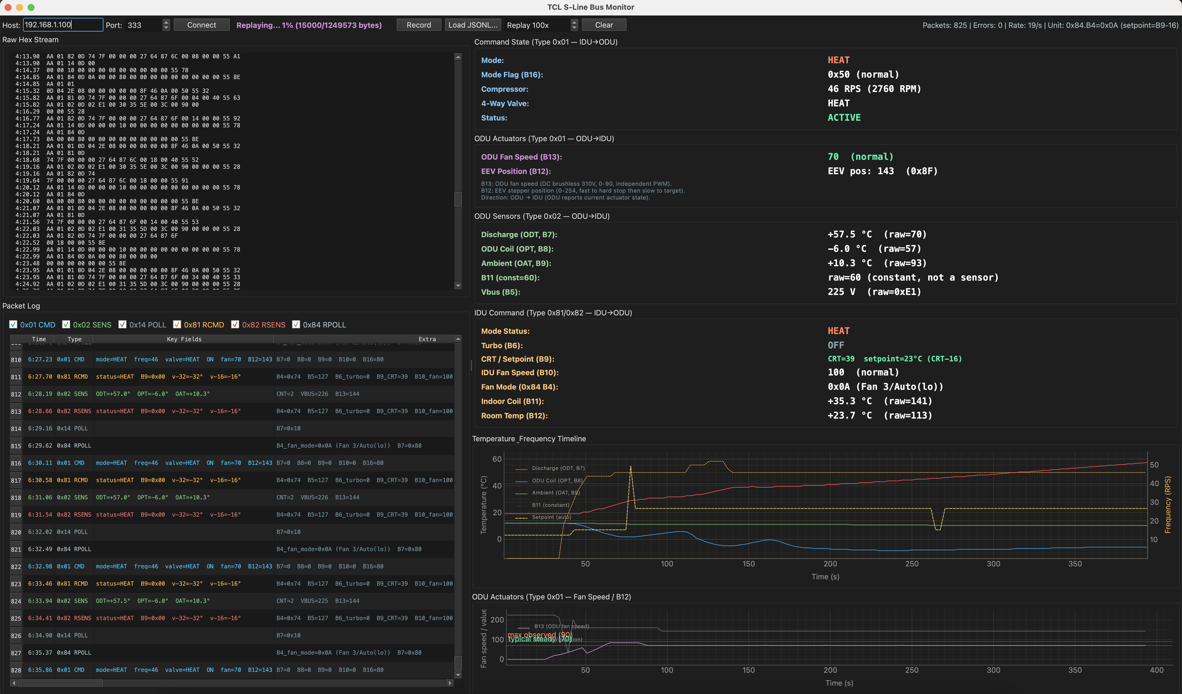
Decoding the Fields: Fan Speed Tests, Mode Cycling, and an Overnight Capture
The fun part was correlating bus data with physical observations. I systematically cycled through every mode (heat, cool, vent, dehumidify, standby) and fan speed (level 1 through 5, auto, turbo, super silent) while capturing the bus data. Each change produced clear byte transitions that identified the field mapping.
Some highlights:
Setpoint encoding surprise: Byte 9 in the response packets (0x81/0x82) is NOT the raw setpoint temperature. It's the CRT (Compensated Room Temperature) = setpoint + a fan-speed-dependent offset. Lower fan speeds get larger offsets (up to +48 at "super silent") to compensate for air stratification at the room temperature sensor. Took a while to figure out why the "setpoint" kept changing when only the fan speed changed!
B5 in 0x02: Initially labeled "unknown status byte", ranging 223-230. Turns out it's literally the AC mains voltage in volts — confirmed by variac test. 229V in standby, 225V at moderate load, 223V at turbo (voltage sag under compressor current draw). A free power quality monitor on the bus. At least with newer units, my older bedroom one is in the 145ish area but I didn't bother to pull out the variac on this one to get the transfer function.
An overnight capture (7.4 hours, 55836 packets, zero checksum errors) while heating at 24C with outdoor temps dropping from 12C to 6C showed the outdoor sensors tracking the ambient decline. The initial temperature encoding assumptions (val-50, (val-68)/2) turned out to be completely wrong, but the correlation was visible because any monotonic transform preserves the shape.
A subsequent water bath calibration (17-95C, all three ODU NTC sensors) revealed the actual encoding: the manufacturer simply transfers raw 8-bit ADC values over the bus. No temperature conversion, no offset, no scaling. The TMS320 MCU reads the NTC voltage divider and puts the raw ADC byte straight into the packet. The IDU firmware presumably converts to temperature locally. This also resolved the B7/B8 sensor assignment ambiguity and the supposed "firmware conversion" on the discharge channel - there is none. The three sensors are: B7 = discharge (20k NTC + 2k pull, CN8), B8 = outdoor coil (5k NTC + 5.1k pull, CN9), B9 = ambient (5k NTC + 5.1k pull, CN9). Steinhart-Hart coefficients for each sensor were fitted from the calibration data, allowing conversion from raw bus values to temperature in the ESP32 firmware.
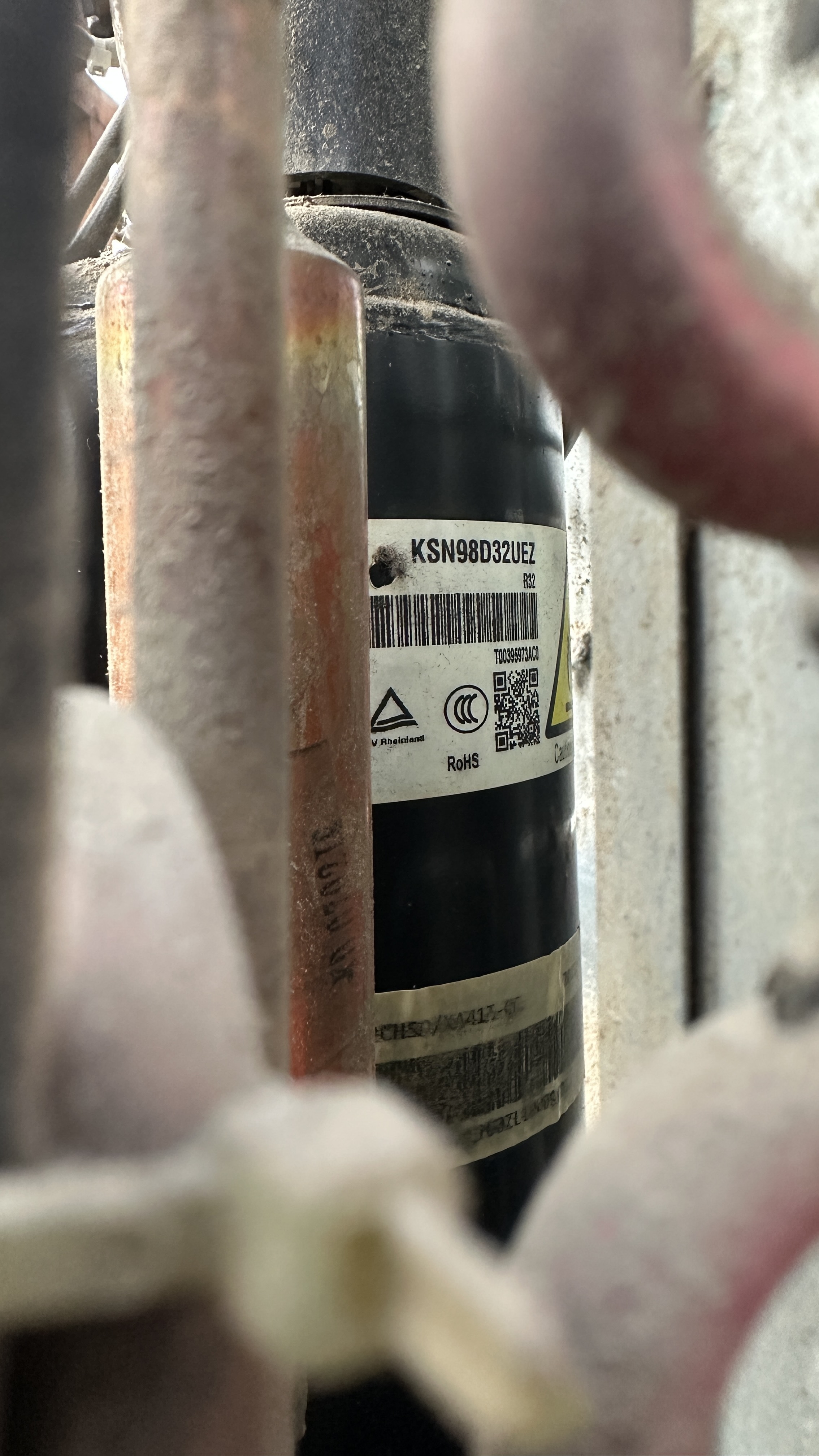
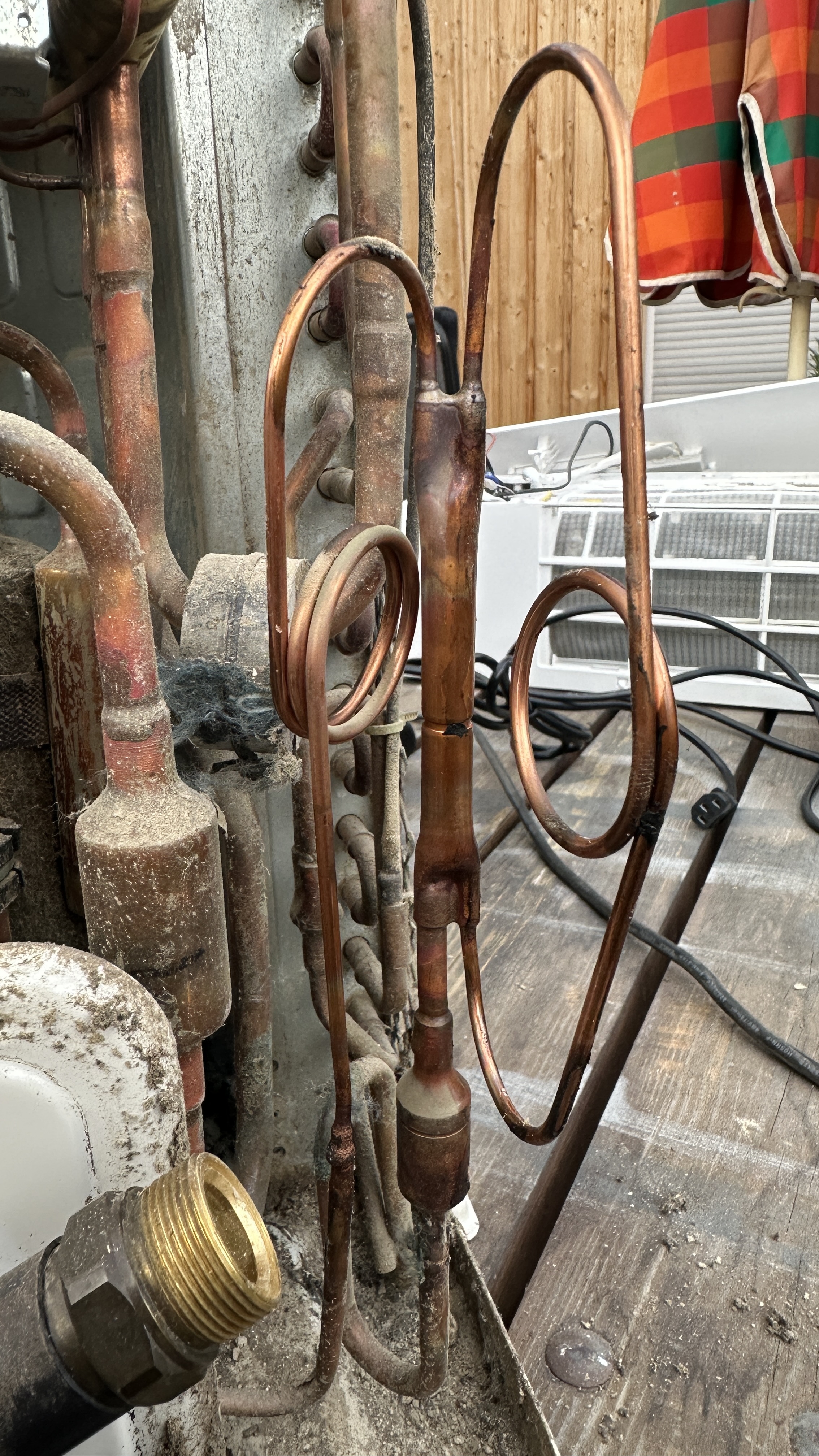
GMCC KSN98D32UEZ compressor (9.8cc, 20-120 RPS) and the bidirectional dual capillary with check valves to give different restrictions in heating and cooling mode! And yes, the "one year old" unit is rather filthy! I picked it up near a construction site where loads of soil were moved around and that's what the whole unit is packed with: lots and lots of soil! Could be worse :-)
Plot Twist: The ODU Is the Brain
The original assumption was that the IDU contains all control intelligence and the ODU is a dumb actuator. This turned out to be backwards. By tapping the sniffer optocoupler in parallel with each unit's TX opto LED individually, I could unambiguously determine who sends which packets. The ODU sends 0x01 (reporting its current actuator state: compressor frequency, valve, EEV position) and 0x02 (raw sensor readings). The IDU sends 0x81/0x82 (mode, setpoint, fan speed, room and coil temperatures).
The clincher: looking at the overnight capture data, the IDU's CRT setpoint byte stays rock-solid at 40 while the ODU independently ramps compressor frequency from 0 to 54 RPS and back. There is no frequency command anywhere in the IDU packets. The ODU's TMS320 DSP runs its own PID loops, determines the compressor speed, manages EEV positioning, and handles defrost all autonomously. The IDU is essentially a smart thermostat: it relays the user's mode and setpoint from the IR remote, and reports indoor room and coil temperatures. In hindsight, it makes perfect sense as�� the TMS320 is massive overkill for a "dumb actuator", and multi-split systems exist where one ODU serves multiple IDUs, which only works if the ODU contains the control logic.
Simplified Hydronic Conversion
This discovery completely changes the hydronic conversion strategy. There's no need to reimplement PID control loops, superheat management, defrost logic, or frequency ramping in an ESP32. The ODU handles all of that internally. The simplest approach doesn't even require touching the bus protocol: keep the IDU connected, set it to 30C heat mode, and replace the room temperature NTC with a digital potentiometer controlled by an ESP32. Feed a fake "room temperature" that's always a few degrees below the setpoint and the ODU keeps heating. Bring it closer to setpoint and the ODU throttles back. For PV-optimized operation, the ESP32 adjusts the fake delta-T based on Tibber dynamic pricing or local PV surplus — more solar available means more fake cold room, means more compressor power consumed. A plate heat exchanger on the indoor coil with a temperature-controlled metering pump on the water side completes the hydronic interface. With discharge temperatures hitting 74C during normal heating, there's plenty of thermal headroom for a plate HX — even with 15-20C approach temperature, that's 50-55C water, more than enough for floor heating.
Cross-Unit Validation: The Firmware Has Real Superheat PID
Connecting the same sniffer to my older R410A TCL bedroom unit� ( the one that actually has an EEV installed) produced the smoking gun. The protocol is identical in structure (same framing, same packet types, same byte positions) despite roughly six years between the two units. But the EEV position byte (B12) behaves completely different: on the capillary tube donor unit, B12 ramps endlessly through the full 0-255 range because the PID integrator has no feedback. On the EEV-equipped unit, B12 converges to a stable operating point (44 at high load, 200 at low load) because the physical valve responds to the PID output. This proves that TCL's "budget" firmware has real superheat PID control built in, it's not using a lookup table. The same universal firmware image runs on both capillary and EEV models; the EEV code is always active regardless of whether hardware is present.
Even better: watching the EEV respond in real time to a setpoint change (26C to 23C) and then a window being closed showed the PID smoothly tracking from EEV=44 (high demand, 70C discharge, 80 RPS) through EEV=200 (moderate demand, 48C discharge, 38 RPS) to EEV=250 (minimal demand, throttling down) before the room hit setpoint and triggered shutdown. The shutdown sequence was the opposite of the capillary unit: the EEV opens wide (250) for 60 seconds of pressure equalization, then closes to a parking position (100) as a sensible default for the next startup. Six years of firmware evolution, but the core protocol survived intact — the hallmark of a stable OEM platform shared across dozens of brands.
What's Next
Solder ULN2003D onto IC10, connect a test stepper to CN7, verify physical EEV control on the donor
Prototype the NTC manipulation approach with a digital pot on the donor IDU
Hydronic conversion: brazed plate heat exchanger, economiser heat exchanger, heater water metering pump, buffer tank plumbing
--- WORK IN PROGRESS, TO BE CONTINUED... ---
(c) DJ9KW